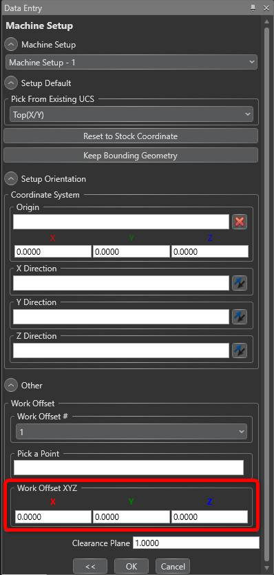
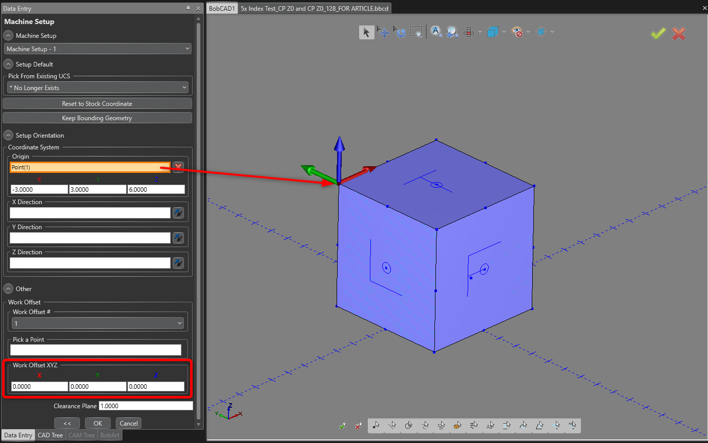
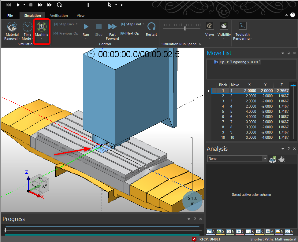
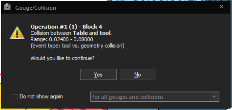
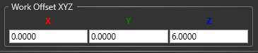
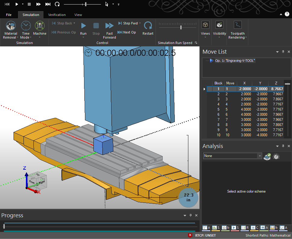
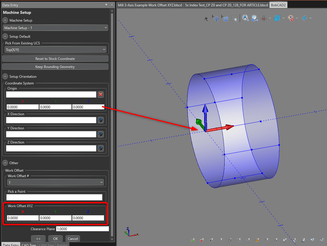
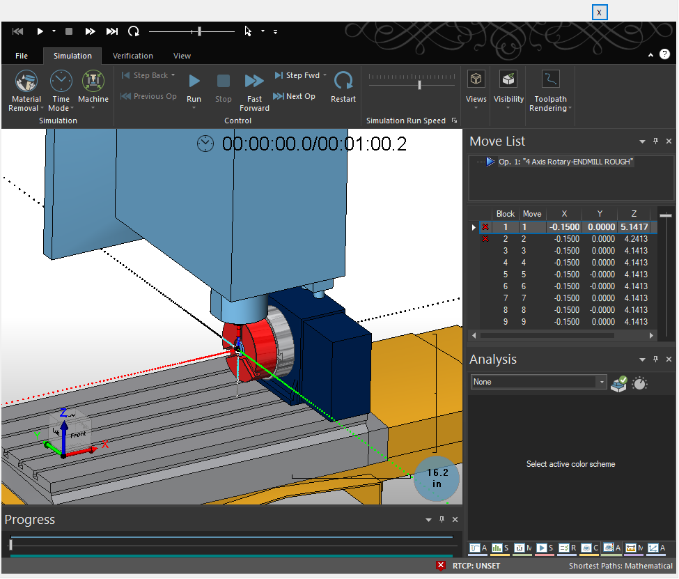
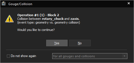
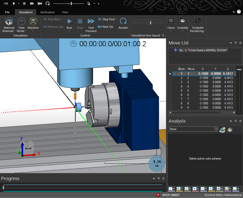
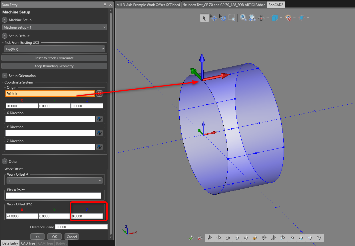
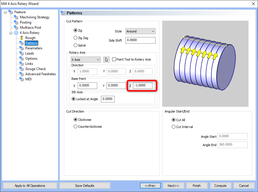
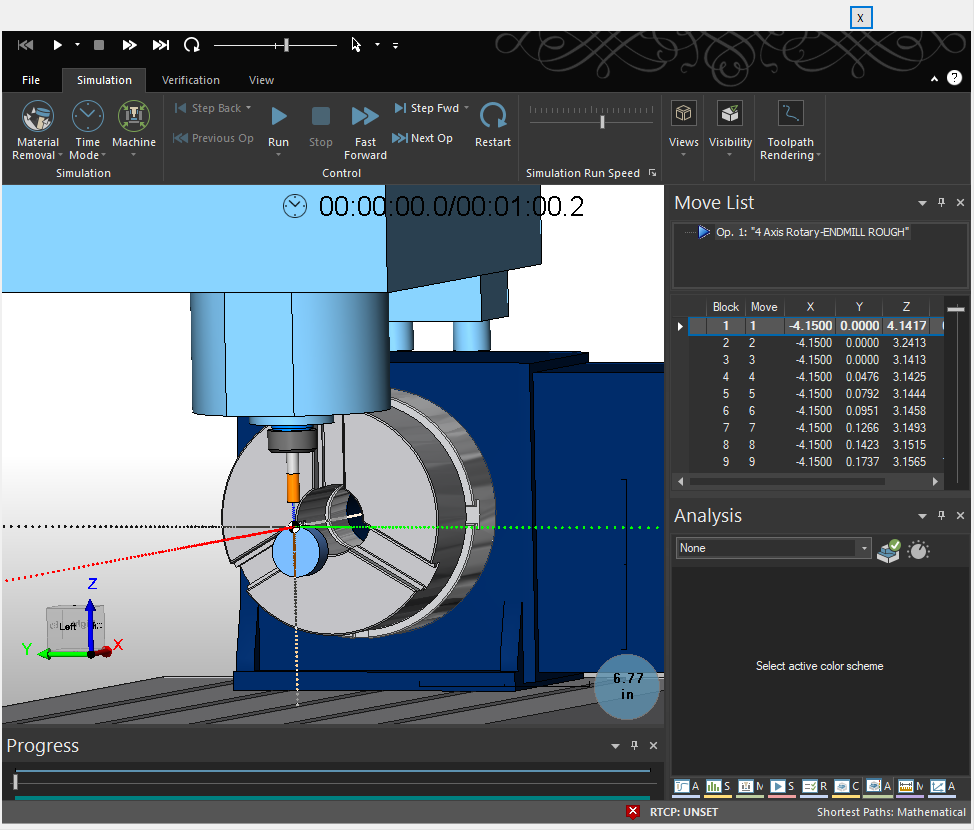
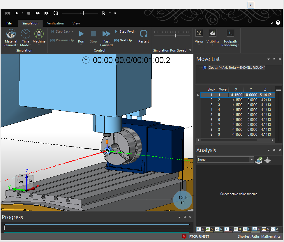
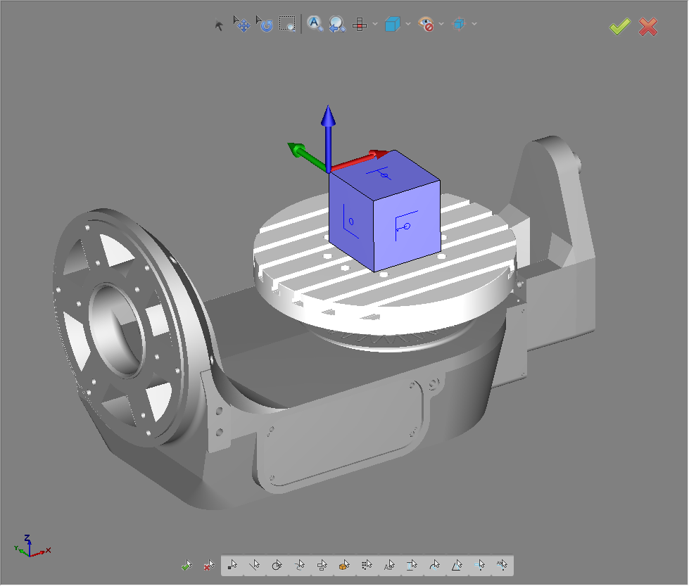
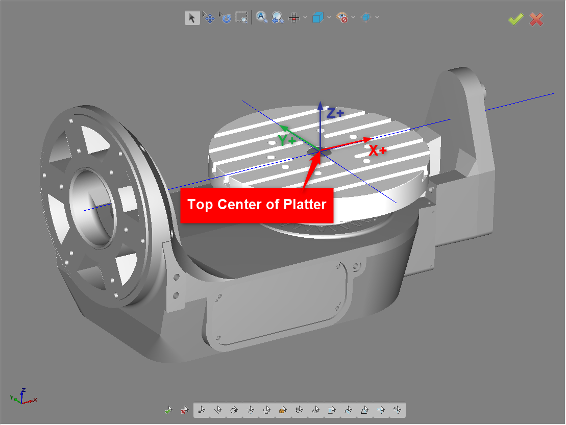
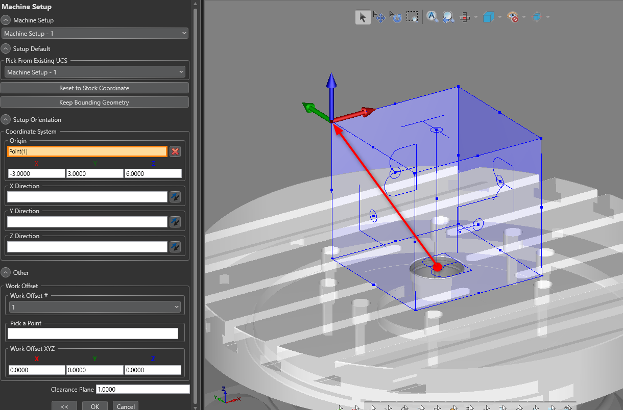
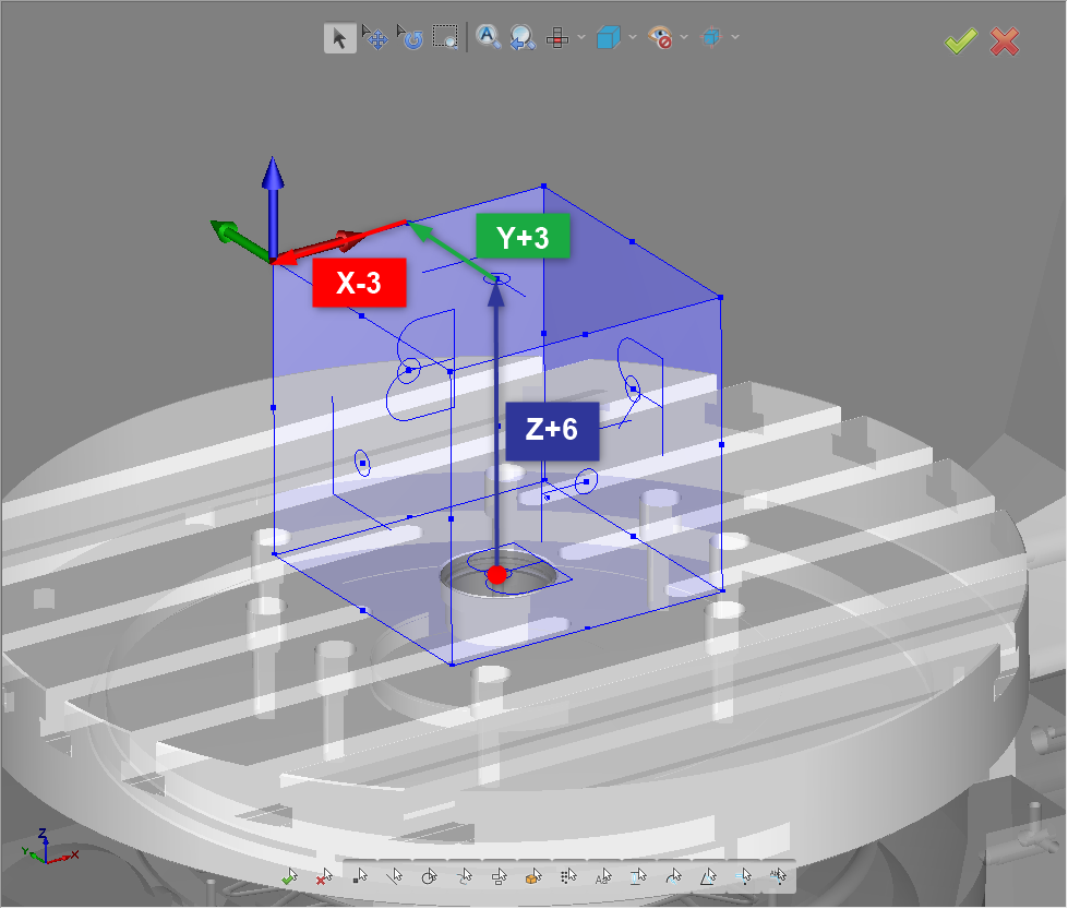
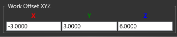
This article will take a deep dive into the Work Offset XYZ section (located on the Machine Setup page) for Milling Jobs. We will go over the process with a 3-Axis, 4-Axis, and 5-Axis milling machine. This Work Offset XYZ section is related to the virtual machine in BobCAD-CAM. These values need to be set up properly to ensure proper g-code and simulation output. Especially, when it comes to using Rotary motion, Indexing, and 4 or 5 Axis simultaneous motion. Please follow through each section in order as each section builds off each other. Pic 1 below shows where this Work Offset XYZ section is located on the Machine Setup page. This page shows up when initially going through the CAM Job Setup or if you right-click on “Machine Setup – 1” in the CAM Tree and click “Edit”. Pic 1 – Machine Setup Page – Work Offset XYZ Section The X, Y, and Z boxes are used to define the distance from what I will call in this article the “Virtual Machine Zero” (this is typically the top and center of the table, NOT the tool home) to the selected Work Coordinate System (WCS) setup on the Machine Setup page in the above “Coordinate System” section. This Work Offset XYZ section is used to link the Virtual Machine Zero in the software to the Work Coordinate System (WCS) you set up on this page. Note: This is Not the Machine Zero on your physical machine, but the Machine Zero of the virtual machine inside of BobCAD-CAM. This is an important distinction. By default, typically, the Machine Zero location for the virtual machine in the software is defined at the Top Center of the table/platter. (See pic. 3 below) Pic 3 – Top Center of Platter for BC_Table_Table Virtual Machine It is important to understand where the Virtual Machine Zero in the software is located so that you can properly set up the Work Offset XYZ section on the Machine Setup page. You will see this being utilized in the coming sections of this article. This Work Offset XYZ section is important to understand because it CAN affect the g-code output. Especially, when it comes to using Rotary motion, Indexing, and 4 or 5 Axis simultaneous motion. In the sections below, this article will describe how the Work Offset XYZ section affects your Milling jobs for 3, 4, and 5 Axis machines. When it comes to 3-Axis machining, this Work Offset XYZ section does not come into play as much as it does for 4-Axis or 5-axis toolpath. This is because there is no need to worry about the positioning of the tool when you have rotated the part with a rotary axis. However, there is one thing you may notice if you have not set this up in the simulation. Let’s take for example the following cube in pic 4. Pic 4 – Work Coordinate System at Top Left of Part – Zero Work Offset XYZ We have programmed the Work Coordinate System at the top left location of the cube because this is where we are going to touch off our tool and set our G54 at the machine. However, we left the Work Offset XYZ section set to X0, Y0, Z0. Let’s say we create an Engraving operation for the top letter “T” of the part and simulate the toolpath. If you have the Machine Sim Pro module, you will be able to view the machine. (See Pic 5 below) Pic 5 – Simulation for a 3-Axis job with WCS at Top of Part and no Work Offset XYZ set up Notice in pic 5 how the stock is inside the table of the machine. And, when you hit “Run”, you will receive the following error: Pic 6 – Simulation Collision between Table and Tool Error This is happening because the default Virtual Machine Zero in the software is located at the Top of the Table. So, this is happening for two reasons. 1. the WCS was set up at the top of the part, and 2. The Work Offset XYZ section on the Machine Setup page is set to zero. Now, of course, you can choose to ignore this error and continue through the simulation. However, to remove the error, navigate back to the Machine Setup page in the job. You will want to adjust the Z value by AT LEAST the thickness of the stock (more if the part is set up in a fixture) to move the stock up out of the table. In our case, the thickness of the Stock is 6 inches. So, we can just set the Z value to a positive 6. Pic 7 – X+6 Work Offset XYZ section of Machine Setup page If you now simulate the toolpath, the Part will be up out of the part, and you will no longer receive the error when running the job. Pic 8 – Machine Simulation Pro with Part above table. So, in conclusion, for 3-Axis Vertical Mill jobs, you simply need to adjust the Z value by a positive value that is at least the thickness of the stock to avoid getting the Collision between Table and Tool Error in simulation if the WCS was set to the top of the stock. Note: If it is set to the bottom of the stock, we will not have to add a Work Offset XYZ Z value because there is no additional shift needed to move the stock in simulation. When it comes to 3-Axis, the g-code is UNAFFECTED no matter what value is set in the Work Offset XYZ section. This is different from 4 and 5-axis toolpath where it can be affected. This is simply for simulation purposes to be able to properly see and simulate the job. When talking about using a Mill 4-Axis machine and toolpath, this is where you might start seeing an issue with posting your g-code if you have the Work Coordinate System setup in a specific way. Let’s take a look at a basic example with a rotary part. Pic 9 – Machine Setup page with WCS set to the front of part at the center of rotation and Zero Work Offset XYZ If you look at Pic 9 above, this would be a standard setup for a Mill 4-Axis machine with an X Rotary axis. The WCS is placed at the front center of the part (If the Rotary Unit is located to the right of the Operator on the physical machine). Let’s leave the Work Offset XYZ set to zero for now. If we apply a standard 4-Axis Rotary toolpath to the job and simulate the toolpath, we will see a similar problem as we did in the Mill 3-Axis example. (See Pic 10 below) Pic 10 - Simulation for a 4-Axis job with WCS at Front Center of Part and no Work Offset XYZ set up Similarly, if you try to “Run” a simulation, you will get a Collision between rotary_chuck and zaxis error as you see below: Pic 11 – Simulation Collision Error To remove this error, you simply need to adjust the Work Offset XYZ X value. Since the X-axis arrow for the WCS is pointing toward the chuck, we need to use a negative X value to move the stock out of the chuck. In this example, the part is 1-inch long. I will set the X value to -4.000 to move it out of the chuck. The same rules apply as in the 3-Axis example. So, therefore I made the X move further away from the chuck. You can account for a fixture or jaws to get a more realistic view of where the part is actually located and view it in the simulation. Pic 12 – X-4 Work Offset XYZ section of Machine Setup page Pic 12 – 4-Axis Rotary simulation with proper Work Offset XYZ X value This works similarly to 3-Axis in that all we are doing is moving the part out of the machine for simulation purposes to get a better and more accurate view of the part in our simulation. With this X value, the g-code is also UNAFFECTED no matter what X value is set in the Work Offset XYZ section. HOWEVER, this is NOT the case when it comes to moving the Z-axis. You will see this in the example below. However, to give a brief explanation as to why, it has to do with the Center of Rotation axes. IMPORTANT NOTE: IF you ever move/shift the Work Coordinate System (On the Machine Setup page) off of one of the Center of Rotation axes, you HAVE TO account for that shift in the Work Offset XYZ section to ensure proper g-code output. One example where you will need to make sure that you adjust this Work Offset XYZ section is if you decide that you want to place the WCS at the top of the cylindrical Stock in the Z direction. (See pic 13 below) If you do not adjust the Work Offset there can be a couple different issues that arise. Firstly, you will notice that the toolpath looks strange and the tool orientation is not correct when backplotting (Right-click on the Operation in the CAM Tree and select “Backplot”) or simulating the toolpath. (See pic 14 below) Pic 14 – WCS set to top of stock with no Work Offset Z value set and no shift in the feature. To fix this issue, you simply need to adjust the Base Point inside the Feature 4 Axis Rotary wizard. Go to the “Patterns” page and adjust the Z value. (See pic 15 below) Pic 15 – Base Point Z set to Z-1 In our case, the stock has a 1-inch Radius. Since the WCS is set to the top of the stock, move in a negative direction back down to the center of rotation. This would be Z-1.0000. This will resolve the issue visually in the toolpath. However, when you load a simulation, notice where the part is in reference to the center of rotation. (See pic 16 below) Pic 16 – Simulation with WCS at top of Stock, no Z value in Work Offset XYZ and Base Point moved in the feature As you can see in the image above, this is not what we were after. The part is off-center of the chuck now. When you post out the g-code, you will notice that this is not correct either. It will post the g-code exactly as you see in the simulation. We want the center of rotation to match the center of the stock. The solution is to adjust the Work Offset XYZ Z value to move our center of rotation back down to the actual center of the chuck. Since we set the WCS to the top of the stock, we should move the Z value to a positive 1. As shown below: Pic 17 – X-4 Z+1 Work Offset XYZ in the machine setup page You may ask why this is positive and not negative like in the feature. Important Note: The best way to describe the sign of the values in the Work Offset XYZ is to start from where ever the Center of Rotation is located to move incrementally from there. So, in our case, if we start from the Center of the stock, since this is where we want the center to be located, we will move up a positive Z1.0000 to move the WCS back to the top of the stock. Once we have adjusted the Work Offset Z value to Z1.0000 and keep the Base Point in the Feature set to Z-1.0000, we can now properly simulate and post out the g-code for the job. Pic 18 – WCS Front Top of Stock, Work Offset XYZ with Z+1, Base Point in Feature with Z-1 In conclusion, the Work Offset XYZ values start to really matter when you have a machine that has a rotation axis. It is important to go back through this article and truly understand how this works to avoid any potential errors in the future. Mill 5-Axis jobs may seem more complex to set up, but it is just a matter of applying the same exact principles as above. If you understand how the Work Offset XYZ section works, you can handle any scenario that may arise. Pic 19 below shows an example of a Mill 5-axis job with the WCS located at the Top Back Left corner of the stock. Pic 19 – Mill 5-axis Example Take a second to stop here, review Pic 19 above and think about what the X, Y, and Z shifts should be for the Work Offset XYZ section using the same logic as above in the previous sections. In this example, it is a 6x6x6 cube that is placed at the center of the table with the WCS at the Top, Back, and Left corner of the stock. (Note: You do not need to account for a fixture for this example) -- -- -- -- -- -- -- -- If you are unsure how to approach this or have attempted the figure out the values and are ready to proceed, please continue the article from here. This is where the Top Center of the platter is located. (see Pic 20 below) Pic 20 – Top Center of Platter If we move the WCS to the Top, Back, Left of the stock, this means we are moving in all 3 linear axes X, Y and Z in relation to our virtual machine zero (Top Center of platter). This means we need to apply a shift in all three axes. (See pic 21 below) Pic 21 – Move WCS to Top, Back, Left of Stock From here, we need to adjust the Work Offset XYZ values to ensure proper g-code output and simulation. Adjusting the Work Offset XYZ will allow us to properly account for the shift off of the Virtual Machine Zero and thus get proper g-code output when it comes to toolpath that involves rotating the Rotation axes. To do this, start from the Top Center of the platter and incrementally move up to the WCS you set up in the job for each axis. Pic 22 – Work Offset XYZ values in the Machine Setup Page To get the Top, Back, and Left corners of the stock, if we start from the Top Center of the platter, we will move Z +6, Y +3, and X -3. Pic 23 – X-3 Y+3 Z+6 Work Offset XYZ section The reason this is needed is so that the software understands where your center of rotation axes are located in the software. You do not need to know where the true center of rotation axes are located on the machine since the posting department should have already set this up for you in the Machine Definition when you sent them the Center of Rotation forms. Center of Rotation forms can be found in the "Post Request Forms for Multi-Axis Mill/Router" tab: Please fill-out the Multi-Axis Mill/Router Post Request form as well as the Center of Rotation from for your specific type of machine and send this to our posting department with the following contact info. Phone Number: (727) 489 - 0003 Email: [email protected] or [email protected] Submit through the Support Site: HERE If you have not filled out the Center of Rotation forms yet for your 5-Axis machine, this is very important to ensure proper g-code output for Rotary motion, Indexing, and 4 or 5 Axis simultaneous motion. Please take the time to fill out this information correctly and send them back to our Posting team for further assistance. This only needs to be done one time, and once set up and tested, you can be confident that the values being posted out are correct for your machine. All machines have slightly different center of rotation pivot distances, even if it is the exact same Machine Make and Model. Some machine dealers may even provide this info for newer machines, so you do not have to calculate them yourself. So, be sure to check with your machine dealer or manufacturer for more info on this. Having the proper center of rotation values from the machine together with using the Work Offset XYZ section is vital in getting the proper g-code moves posted out in the g-code. You may ask, but I use TCP and my XYZ coordinates are in relation to the WCS. This does not effect me. This is correct. TCP coordinates are in relation to the Work Coordinate System (WCS). When TCP is enabled, the machine does all the necessary calculations to account for the centers of rotation of the machine. However, the machine is not ALWAYS in TCP mode in the NC program. TCP mode is typically only enabled for the actual toolpath motion you see in the software. However, TCP can be disabled or enabled at the beginning or in-between Toolpath Operations. You also may have TCP turned on for one Operation and not another. There are many cases where you aren’t always using TCP, and in those cases, it is important that these numbers are output properly to avoid any scrapped parts or collisions. The Work Offset XYZ section on the Machine Setup page is an important section to understand, especially when it comes to 4 and 5-axis machines. These values need to be set up properly to ensure proper simulation and g-code output. If you are using a toolpath that involves Rotary motion, Indexing, and 4 or 5 Axis simultaneous motion, make sure you understand this topic to ensure correct g-code output. Use this article as a guide to help understand how to deal with errors in the simulation and get proper g-code output for your machine.
If you need further assistance, please contact our support team at (727) 489 – 0003 or [email protected]Knowledge Base Articles
Machine Setup Page - Work Offset XYZ
Key Topics Covered:
General Overview

Mill 3-Axis Example
Mill 3-Axis with Work Coordinate System (WCS) at Top of Stock
Mill 4-Axis Example
Mill 4-Axis Machine with Work Coordinate System (WCS) at Front Center of Stock

Mill 4-Axis Machine with Work Coordinate System (WCS) at Front Top of Cylindrical Stock
 Pic 13 – WCS at the Front Top of the Stock No Work Offset Z value set
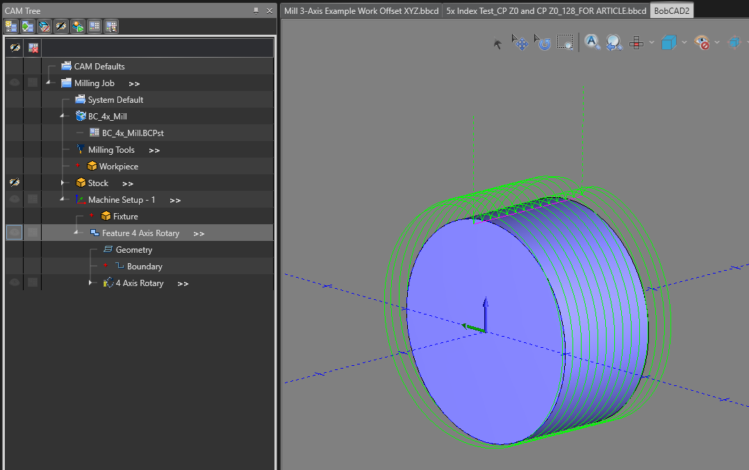

Key takeaways:
Mill 5-Axis Example
Mill 5-Axis with Work Coordinate System (WCS) at the Top, Back, and Left of the Stock
Question 1: What values should be placed in the Work Offset XYZ section below?

Mill 5-Axis Work Offset XYZ section Solution:
Solution 1: These would be the values you would place in the Work Offset XYZ section.
Mill 5-Axis Center of Rotation Forms and Why They Are So Important?
Conclusion:
Key Takeaways:
BobCAD-CAM V36
Getting Setup
Quick Tips & Tricks
The BobCAD Basics
Advanced Topics
Computer Issues
NC Editor
Post Processor
Our Forum
Created: May 17, 2023