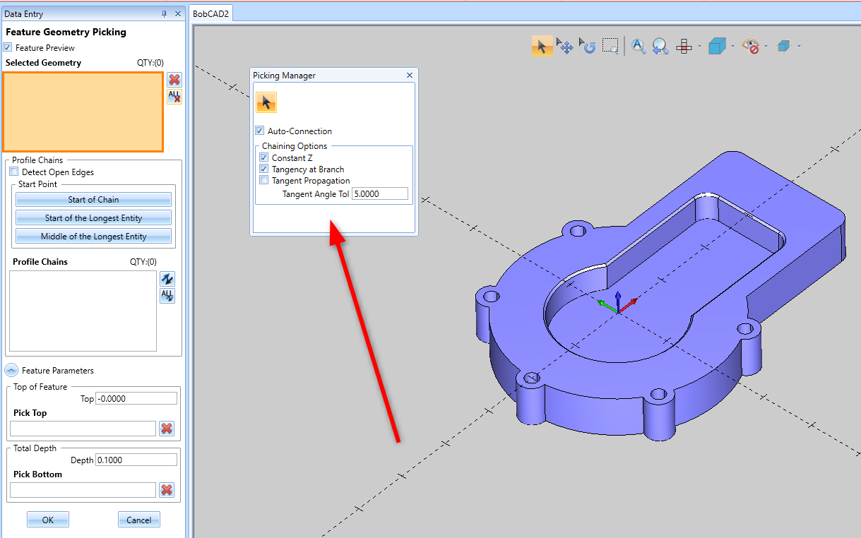
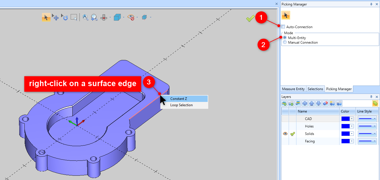
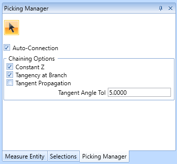
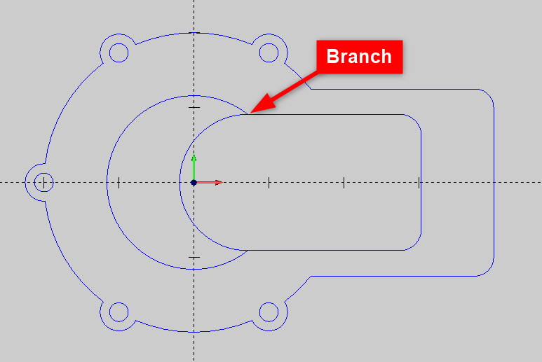
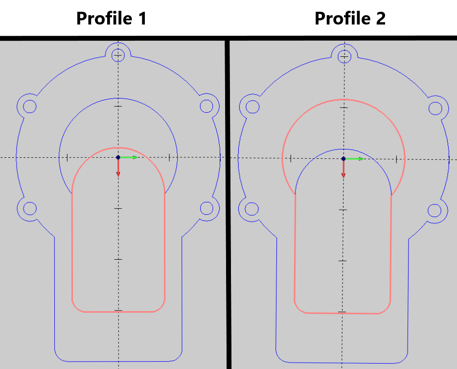
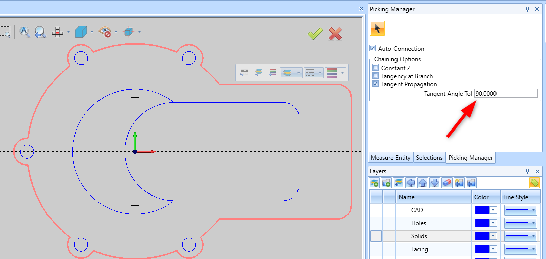
The picking manager is a new tool in BobCAD-CAM V36 designed to make it easier to select entities in the software. The new chain selection options give you an enormous amount of power to select entire chains, from wireframe and solids alike, with speed and ease! Whether you're selecting geometry for CAD features or assigning geometry to CAM features, these new options have you covered! Pic 1 – Picking Manager Window The picking manager is a window in the software that pops up whenever using anything that requires selecting geometry, like when picking geometry for a feature, or when using a CAD function like Translate to select entities to move. This Picking Manager window works just like the other windows (eg. Layers, CAM Tree) in the software. You can move and place it anywhere in the software. It will stay in the location you place it for any future selections. Hold Left-Click on the top of the Picking Manager window. You will see arrows pop up in the software where you can drag your cursor into to place the window. In the example below, we are dragging it into another window to move it to the desired location. Pic 2 – Drag Picking Manager into another window Next time the picking manager pops-up, it will show up in the location you moved it. The picking manager has several options that you can use to make it easier to select geometry. This section will describe the different ways you can utilize the tool. If you are coming from an older version of the software that does not have this tool, you can still use the old selection picking method by unchecking, “Auto-Connection” and enable, “Multi-Entity” Pic 3 – Old Selection Picking Method This will allow you to right-click on a surface edge and select “Loop Selection” or “Constant Z”. Or, Hold SHIFT + Left-Click on a wireframe to chain select your entities. You can also drag a box over the desired geometry to select entities. This was the old picking selection method. However, to take advantage of this new tool, you can use the other options in the manager. Let’s first cover the Auto-Connection page: Pic 4 – Auto-Connection Picking Manager The most common way to select geometry is by using the “Auto-Connection” page. In this example, let’s keep the default options enabled on this page where “Constant Z” and “Tangency at Branch” are enabled. Now, simply click on the surface edge and observe how it chain-selects around the part automatically in one click. Pic 5 – one click to chain select surface edge This works the same for wireframe geometry as well. Pic 6 – one click to chain select for wireframe Constant Z works well for geometry that is flat, but what if we have a curved profile that we want to select? If you have a curved geometry that you want to select, simply uncheck “Constant Z” and click on your surface edge or wireframe geometry. Pic 7 – one click selection varying Z height Now that we understand the basic functionality of the picking manager, it’s time to discuss what the additional Tangency options are used for. Tangency at a branch is an option that is used to decide how to pick a direction of the geometry selection if the software runs into a scenario where there is a "branch". Take a look at the picture below. Typically, your geometry is either an open geometry, where the start and end point of the geometry are not connected, or, it is a closed geometry (similar to the outer profile in pic 8) meaning that there is no exact start and end to the profile. It is fully connected or "closed". However, there is a third type of geometry that can also occur. In the image below, there can be cases where there are points in the geometry that split off in multiple directions. These intersections are called, “branches”. Pic 8 – example of branch geometry In this example, there are two possible closed profile chains. Pic 9 – two potential closed profile chains So, how does the software pick which path that the selection travels down? This is where the “Tangency at Branch” and “Tangent Propagation” options come into play. Let’s start by disabling all Chaining Options and see what happens. Pic 10 – No tangency selected In the gif above, notice how the selection stops at the Branch point location. The Tangency options are there to handle branching geometry. With all tangent options disabled, the selection will simply stop if it encounters a branch point. Now, let’s enable, “Tangency at Branch” and select the geometry in the same way. Pic 11 – Tangency at Branch As you can see in the gif above, with Tangency at Branch enabled, whenever we encounter a branch now, if it finds a direction that would be tangent to the chain profile, it will continue down that path and close off our profile in this example. Tangency at Branch, handles branching scenarios, but what is “Tangent Propagation” used for? Tangent Propagation is used to select geometry that is tangent throughout the profile. Let’s try to select the outer profile of the part with “Tangent Propagation” disabled and enabled. Pic 12 - Tangent Propagation Example With “Tangent Propagation” disabled, the picking manager does not pay attention to non-tangent areas in the profile. So, the whole profile is selected. However, with this option enabled, whenever the profile reaches a non-tangent location, the geometry selection stops there. You can also set the amount of tangency that the manager will consider by setting up the “Tangent Angle Tol”. This is the degree at which you want to manager to by-pass Tangent Propagation and just continue the profile selection anyways. If we set this value to a high value like 90 degrees, notice in the picture below how it will select the whole profile again even when Tangent Propagation is turned on. Pic 13 – Tangent Angle Tol All the options in the picking manager are designed to make it easier to quickly select geometry without having to do a bunch of extra work like organizing your geometry in layers or manually selecting each individual entity. However, what if you have gone through all the options in the article and you are still not able to select the exact chain you want to select? What if your profile has a combination of constant Z locations, multiple branch directions, etc? This is where the “Manual Connection” option comes into play. This tool is used to manually set up your chain. It allows you as the user to decide what the best chain path is for your geometry. Let’s see how this is used in our example. Pic 14 – Manual Connection With Manual Connection enabled, you can click on your profile and a chain will automatically be created. Then, continue to click along the profile and decide for yourself which direction you want to the profile to go. Press “End Chain” when done. You can also use these options together. Pic 15 – Constant Z with Manual Connection As you can see in the example above, you can string multiple selections together for your geometry selection if necessary. This document should give you a good understanding of this picking manager and should speed up your workflow once you understand how it works. If you ever need any further assistance, please do not hesitate to reach out!
If you need further assistance, please contact our support team at (727) 489 – 0003 or [email protected]Knowledge Base Articles
Picking Manager – How it Works
Moving the Picking Manager Window
Picking Manager Options
Old Picking Selection Method
Auto-Connection:
Constant Z:
No Constant Z selection:
Tangency at Branch:


Tangent Propagation

Manual Connection:
BobCAD-CAM V36
Getting Setup
Quick Tips & Tricks
The BobCAD Basics
Advanced Topics
Computer Issues
NC Editor
Post Processor
Our Forum
Created: October 20, 2023