Knowledge Base Articles
- BobCAD-CAM V36
- Getting Setup
- Quick Tips & Tricks
- The BobCAD Basics
- Advanced Topics
- Computer Issues
- NC Editor
- Post Processor
- Our Forum
Wire EDM Geometry Creation / Selection (4-Axis)
This article will demonstrate how to select or create appropriate geometry for use in upper and lower geometry as well as sync lines using 4-axis Wire EDM features to generate the corresponding toolpaths. Two examples will be presented to illustrate this process.
The first example will illustrate the use of geometry from a 3D model to generate the toolpath. The second example will demonstrate a more complex scenario in which upper and lower geometry must be created before the toolpath can be generated. Both examples are shown below.
You can download the finished example parts here: Example Part 1 | Example Part 2
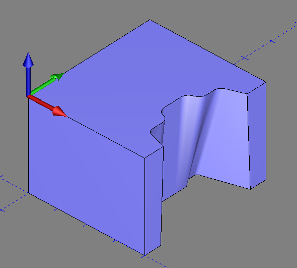
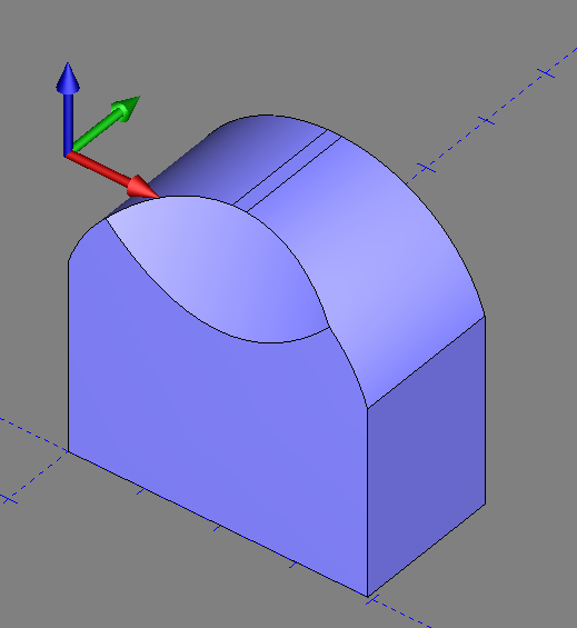
Pic 1 – 4x Wire EDM Example 1 Pic 2 – 4x Wire EDM Example 2
Example 1 – Basic Geometry Selection
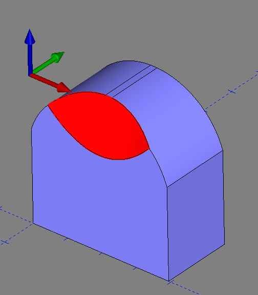
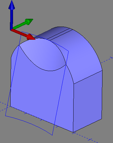
In this first example, we want to use a 4 Axis Open feature to create toolpath for the highlighted surface in the Pic 3.
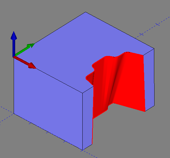
Pic 3 – Highlighted Surface to Machine
We can utilize the edges of the 3d model to select the Upper and Lower Geometry for the 4x Open feature. This is because the edges of the surface are on the top and bottom planes of the part (See Pic 4 below).
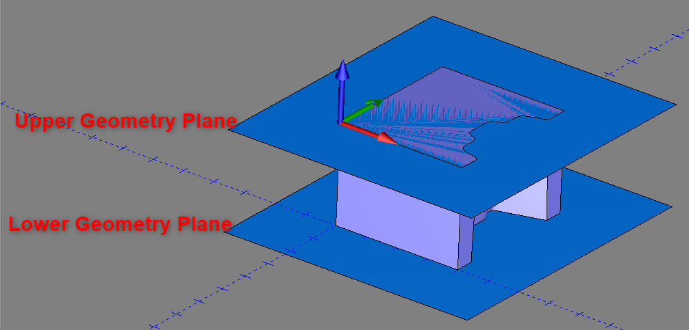
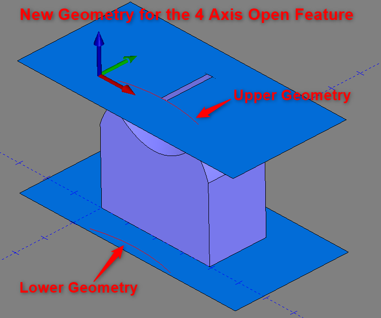
Pic 4 – Upper / Lower Plane for Geometry Selection in 4-Axis Wire EDM Operation
Imagine an Upper Plane on the top of the part (Or stock) and a Lower plane on the bottom of the part/stock like in Pic 4 above. If the top and bottom edges of the cut surface are not on the same plane, then this means you will more than likely need to create new wireframe geometry to reflect that. See Example 2 which shows an example of this.
However, in this example, the top and bottom edges of our cut surface are indeed on the same plane as the Upper and Lower planes in pic 4. So, there is no additional geometry that needs to be created.
Let’s go ahead and create a toolpath for this example so that you can see a general workflow of how to select the geometry needed for this 4-axis Wire EDM Open cut.
Step-by-Step
As stated above, you can use the edges of your 3d model to select your Upper and Lower Geometry for the toolpath. However, to keep things clean and organized, we will extract the edges off the model and utilize this wireframe geometry instead. In Wire EDM, all that is needed is wireframe geometry to generate toolpath. This will help us keep our geometry organized using the “Layers” manager and allow us to easily select geometry.
Wireframe Geometry Creation
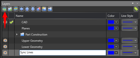
1. Navigate to the “Layers” window. Press the “New Layer” icon in the top left of the window and create 3 layers named, “Upper Geometry”, “Lower Geometry” and “Sync Lines”
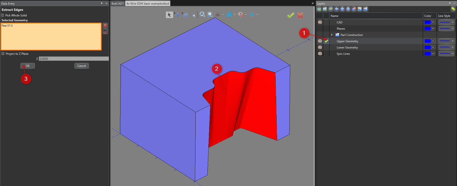
2. Navigate to the Create 2D tab and select Extract Edges ![]()
3. Make sure the Checkmark in the “Layers” window is in one of the newly created layers, select the cut surface, and click the “OK” button to execute the command.
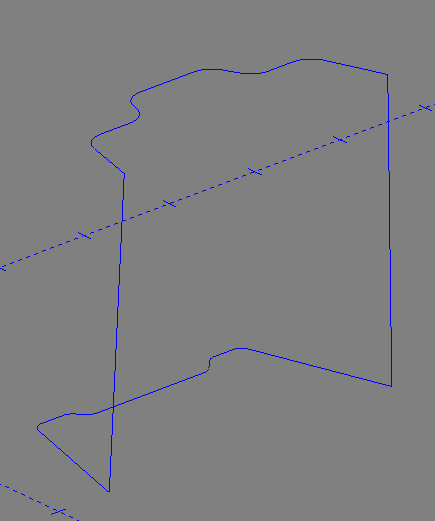
4. Hide the layer that contains the solid model (This example uses the “CAD” layer) by clicking the eyeball icon. ![]() (This blanks out the Solid Model. You should now just see the Wireframe we created)
(This blanks out the Solid Model. You should now just see the Wireframe we created)
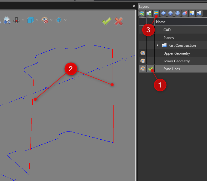
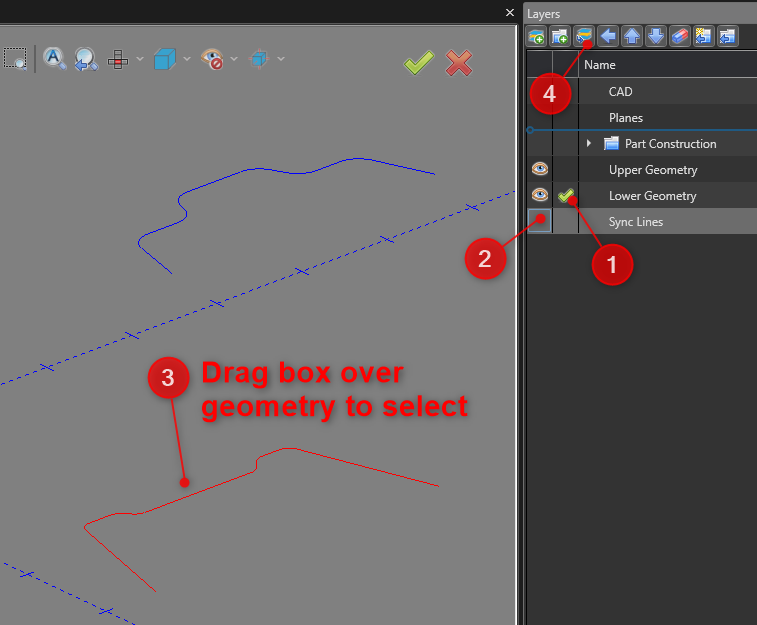
5. Next, place the Checkmark in the “Sync Lines” layer to make it active, select the two lines that connect the top and bottom edges, and press the “Modify to Current Layer” icon shown in the picture below
6. Move the bottom wireframe to the “Lower Geometry” layer by moving the checkmark to the “Lower Geometry” layer, blank out the “Sync Lines” layer, drag a box over the bottom wireframe to select it, and hit the “Modify to Current Layer” button to execute the command.
You should now have each set of wireframe geometry in its corresponding layers. This method makes it easy to work with the geometry when setting up the toolpath. Let’s now select our geometry in the feature.
Geometry Selection for “4 Axis Open” Feature
1. To create a 4 Axis Open feature for this geometry, right-click on “Machine Setup – 1” in the CAM Tree and select “4 Axis Open”.
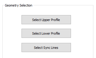
2. On the first “Geometry Selection” page, you can now see the three buttons set up like our Layers we created. Click, “Select Upper Profile”
3. You can now go through the process of blanking out layers where needed to easily select the geometry for each selection. Notice on the left-hand side that you can select the Upper/Lower Geometry and Sync Lines all in the same window. To do this, click inside the box you want to select to make it active (The box should turn Orange indicating that it is active). Add all geometries necessary for the Upper Geometry, Lower Geometry, and Sync Lines box.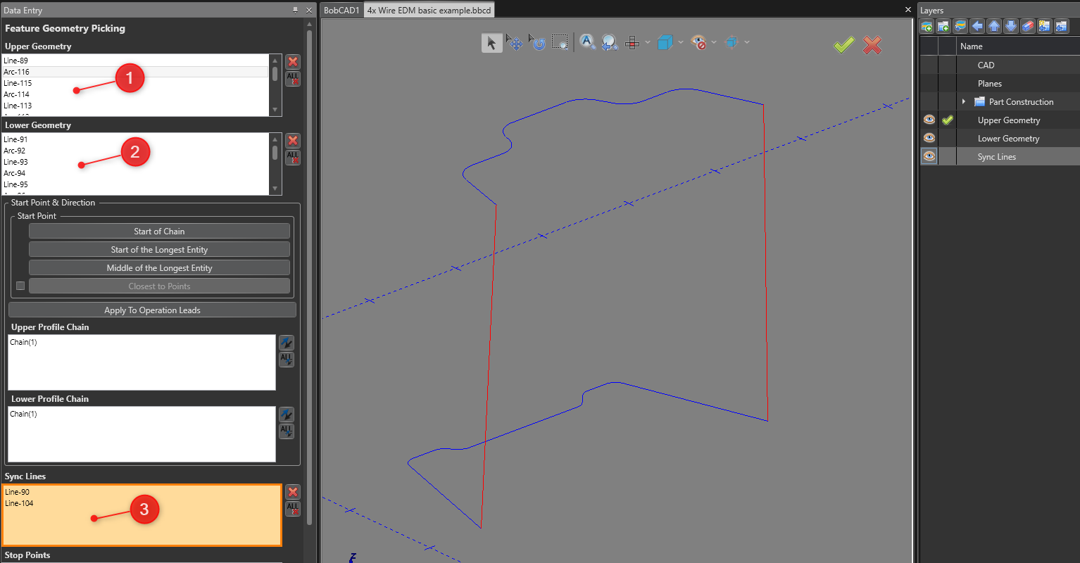
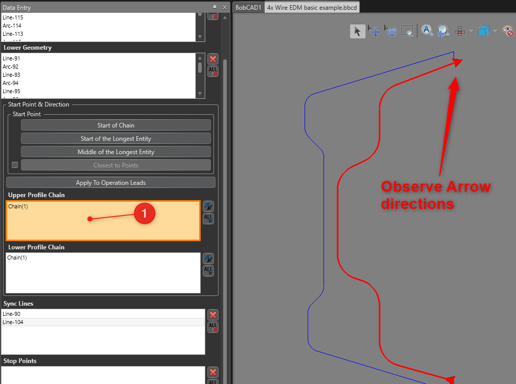
4. Now, you can click inside the “Upper Profile Chain” and “Lower Profile Chain” boxes to view the cut direction. Make sure both chains are facing the same way.
5. Click the “OK” button at the bottom of the left-hand window (Data Entry Window) to complete the Geometry Selection.
6. Set up the feature wizard to the specifications of the job and press “Compute” when finished to create the toolpath.
This is the finished result.
Pic 5 – Computed Toolpath
You can observe that it doesn’t look quite right. The toolpath appears to be inside the surface. This simply means that we need to define more Sync Lines to help the toolpath understand exactly how you want to orient the wire to cut this profile. You can do this by going to “Create 2D” and selecting the “Line” command. Then, go through and create lines and clearly define the wire orientation. Each line represents the orientation of the wire along the profile.
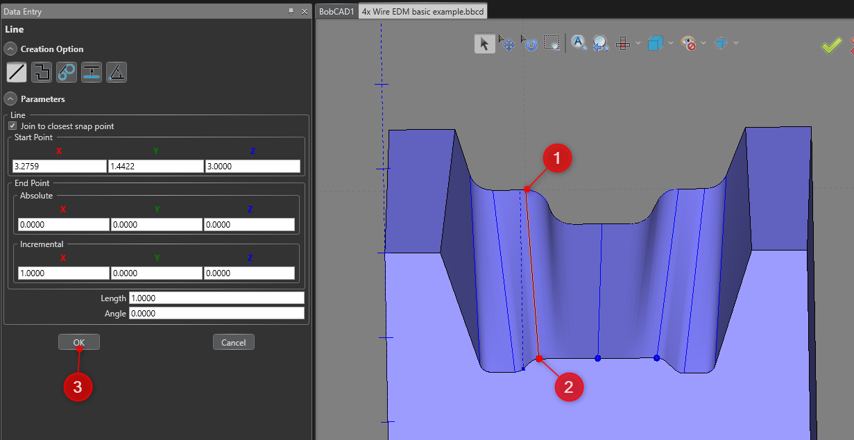
Pic 6 – Defining more Sync Lines
Once you have a good amount of Sync Lines, go back to the “CAM Tree”, right-click on “Sync Lines” in the feature, and click “Re/Select”. Add these new Sync Lines to the selection and press “OK”. Right-click on “EDM 4X Open” in the CAM Tree and click “Compute All Toolpath” to see the finished result. Continue to add more sync lines if needed.
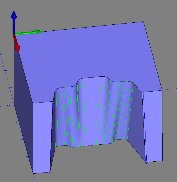
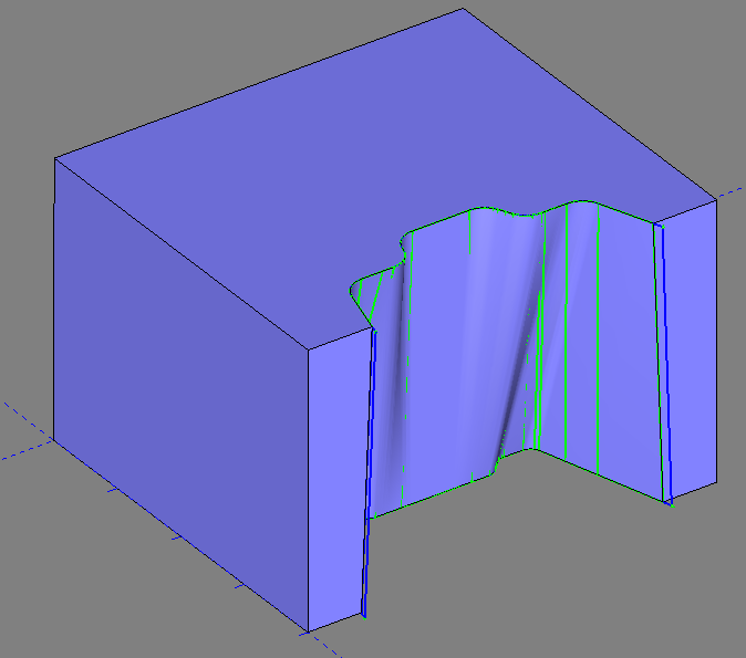
Pic 7 – Computed Toolpath with Additional Sync Lines Added
This concludes the Geometry Selection for Example 1. We covered how to create Wireframe geometry to use in the selection, how to select the geometry when setting up the 4 Axis Wire EDM feature and how to modify the Sync Lines to get a cleaner result. This is the basic method you can utilize to have an organized and efficient workflow. This process will work in most cases for 4 Axis Wire EDM geometry.
However, there is one other scenario that is worth mentioning. That is if the top and bottom edges of the model do not align with the Upper and Lower Geometry Planes shown in pic 4 at the beginning of this article. This creates a unique problem where we need to more clearly define the Upper and Lower Geometries to get the correct toolpath we are looking for. Go through Example 2 below to see how you could approach this type of part.
Example 2 – Custom Geometry Creation
Let’s take a look at the example 3d model below:
Pic 8 – Example 2 model with highlighted cut geometry
Notice how the bottom edge of the highlighted surface is nowhere close to the bottom of the part/stock. The top edge is closer but has the same problem.
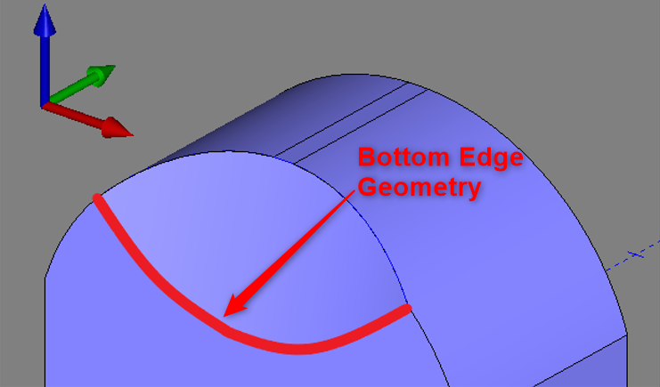
Pic 9 – Bottom Edge of Cut Surface
This type of geometry can be solved in two main steps; Create the Upper and Lower Planes, Create the Upper and Lower Geometry
This method will be to create the XY Planes of the Upper and Lower Geometries. Then, we can utilize the cut surface to “Untrim” it (turn the surface into its’ simplest form) and extend it to intersect the two planes. From there we can use “Intersection Curves” in the “Create 3D” tab for the Upper and Lower Geometry wireframe. Let’s run through this process in more depth below.
1. Create Upper and Lower Planes
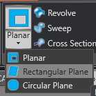
First, create a plane on the top and bottom of the model/stock. You can utilize the “Rectangular Plane” function in the “Create 3D” tab to construct these planes.
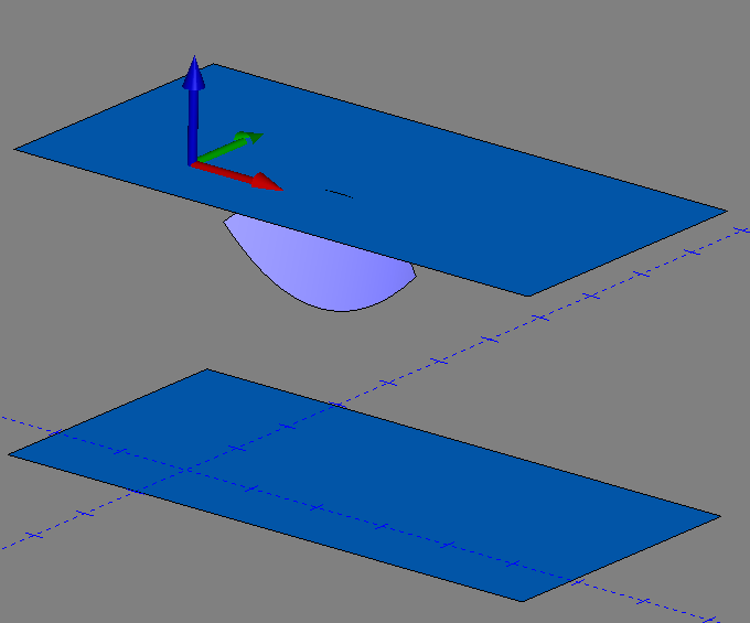
Make sure that the planes are created on the XY plane relative to the Machine Coordinate system and place one on the top and one on the bottom of the part (Or, stock). It should look like the picture below.
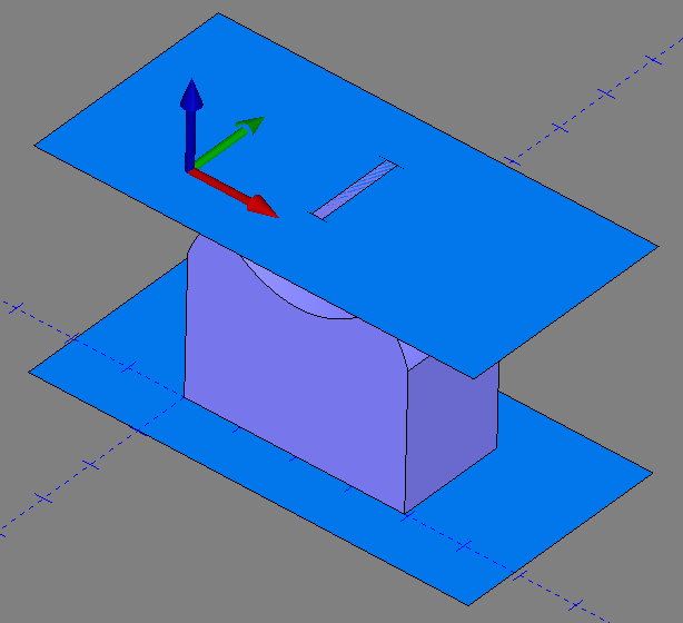
Pic 10 – Upper and Lower Geometry XY Planes
2. Create the Upper and Lower Geometry
Our next task is to extract the cut surface off of the original model. In V35 or newer, you can do this by going to the “Create 3D” tab and using the function “Copy Face”. This will allow you to copy the face off of the original model so that the original model does not have to be modified. (In the older versions, you can copy and paste the original model to a new layer, Unstitch the model and delete all surfaces besides the one you want to keep.)
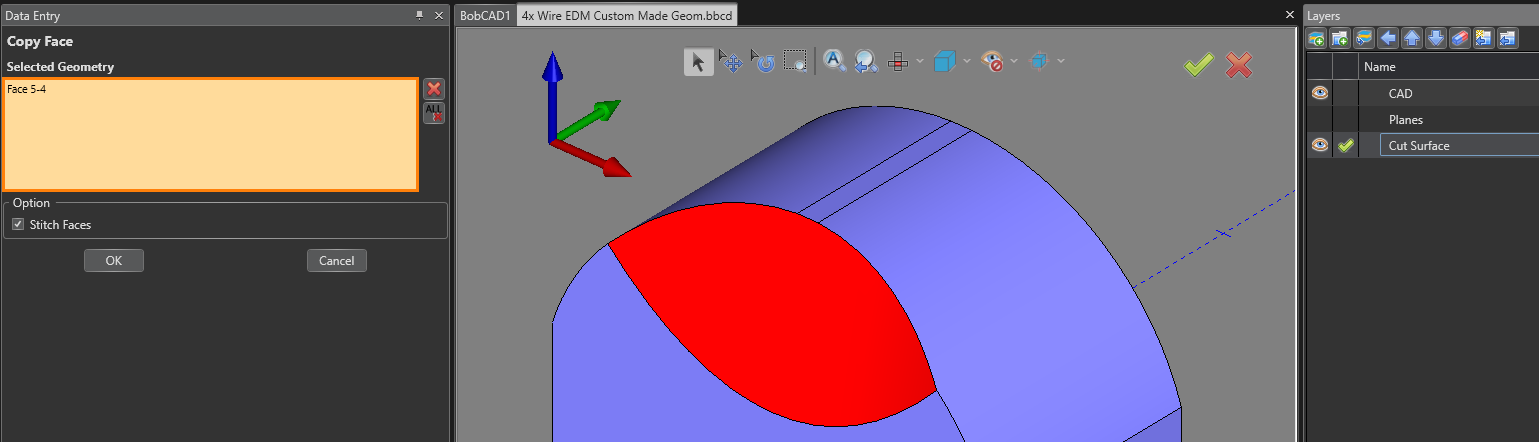
Pic 11 – Copy Face Function
We have now created two planes and extracted the cut surface off of the original model as shown below:
Pic 12 – Upper and Lower Geometry Planes and Cut Surface
Next, we need to extend the cut surface so that it intersects the two planes in both directions. To do this, we first must “Untrim” the edges we want to extend to ensure that the edges will extend along the tapered angle of the surface.
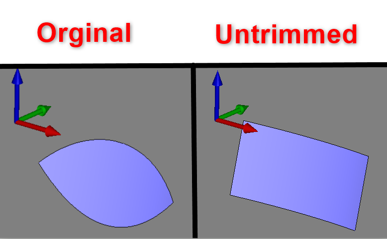
Pic 13 – Original versus Untrim Surface
The technical definition of the Untrim function is that it is a function that returns a surface back to its’ natural boundary. This will always be a rectangular shape.
Whenever you are using the “Extend” function, you may run into an error that states: “Failed in: Only edges on the natural boundary of a surface can be extended”. This is the reason you want to “Untrim” the surface first before extending the surface edge. This will give you a natural boundary.
Now that we have Untrimmed the surface, let’s use the “Extend” function located in the “Create 3D” tab to extend the bottom edge of the surface past the lower geometry plane, as you see in pic 14 below.
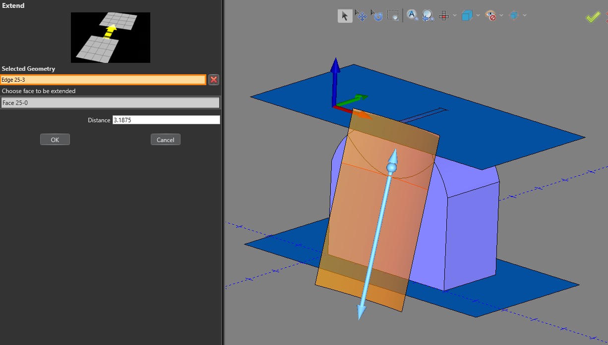
Pic 14 – Extend the Bottom Edge of the Cut Surface to Intersect the Lower Geometry Plane
The upper edge of the cut surface is already intersecting the upper geometry plane. So, there is nothing we need to do there.
The last step is to actually create the Upper and Lower Geometry for the 4 Axis Wire EDM feature by using the “Intersection Curves” function in the “Create 3D” tab.
Click the “Intersection Curves” function and select the cut surface along with the Lower Geometry Plane to create the intersection geometry between the two surfaces. Click “OK” to execute the command. (See Pic 15)
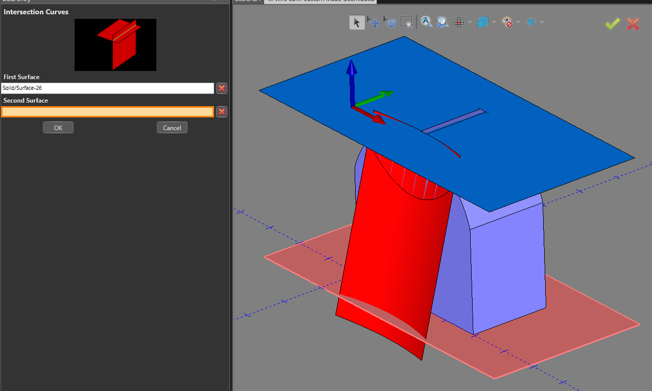
Pic 15 – Intersection Curves: Selecting Cut Surface and Lower Geometry Plane
Do the same for the Cut Surface and the Upper Geometry Plane. Pic 16 and 17 below show what the final result of the new Upper and Lower geometry should look like after all steps are completed.
Pic 16 – Final Geometry used for the 4 Axis Open Feature
Looking at Pic 17 below, you can see how we have also added two sync lines to connect the Upper and Lower Geometry. We now have all the wireframe geometry needed to create the toolpath.
Pic 17 – Final Wireframe geometry used for the 4 Axis Open Feature
Applying the same methods we used for the geometry selection earlier in the article, in the “Geometry Selection for “4 Axis Open” Feature” section, we get the final toolpath in Pic 18.
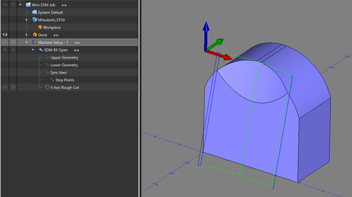
Pic 18 – Final Toolpath for the 4 Axis Open Feature
This article should give you a great overview of how Geometry Selection works in Wire EDM, particularly when creating 4 Axis Toolpath. We covered two examples. The first is a basic 4 axis Wire EDM example and the second shows a more complex geometry that shows how to create good Upper and Lower Geometry for this type of part. These two examples should cover most of what you need to know when selecting geometry in Wire EDM.
However, we do have many other resources online that you can utilize 24/7 to better understand Wire EDM in general. Look through the “Training” tab on bobcadsupprt.com for more training info. You can also check out our Youtube channel (https://www.youtube.com/@BobCADCAM) or our Launchpad platform here: https://launchpad.bobcad.com/
If you need further assistance, please contact our support team at (727) 489 – 0003 or [email protected]