Knowledge Base Articles
- BobCAD-CAM V36
- Getting Setup
- Quick Tips & Tricks
- The BobCAD Basics
- Advanced Topics
- Computer Issues
- NC Editor
- Post Processor
- Our Forum
How to Setup the Machine Coordinate System inside of BobCAM (No Work Offset)
for the Pocket NC 5-Axis Mill Machine
This document will cover the Machine Coordinate System for the Pocket NC 5-Axis Mill machine and will explain how you will set up the Machine Coordinate system inside of BobCAD-CAM (without using Work Offset G54, G55, etc…).
Understanding the Machine XYZAB Zero Orientation

Pic. 1 – Iso View of Pocket NC 5-Axis Machine
Pic. 1 above shows an Iso view of the Pocket NC 5-Axis Mill machine. The positive Z points towards the tool and is horizontal, the positive Y points upwards, and the positive X points away from us. The A-Axis rotation axis rotates around the X linear Axis and the B-Axis rotation rotates around the Y linear axis.
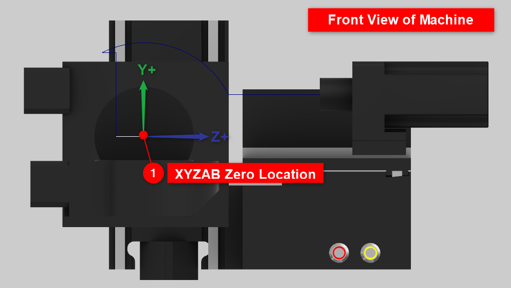
Pic. 2 – Front View of Machine
If you take a look at Pic. 2, notice how XYZAB Zero origin location is above the table of the machine. This is because the Zero position is centered around the A and B Rotation axis. In your Quick Start guide that was given with the machine, you should have a “Measured “B-Table Offset”” value already filled out.
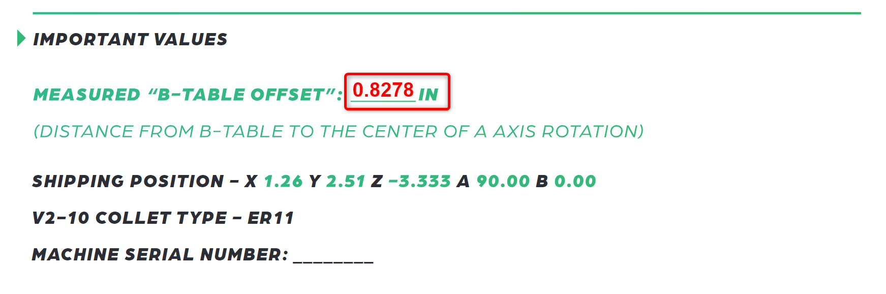
Pic. 3 – Measured “B-Table Offset” in Inches
This B-Table Offset value will be slightly different per machine. So, please make sure you use the value that was provided for you that came with the machine.
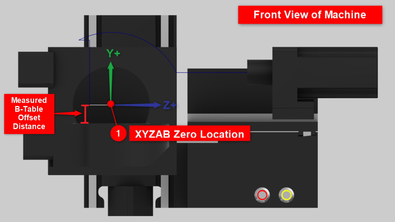
Pic. 4 – Measured B-Table Offset on Machine
If you look at Pic 4, this will show you where this Measured B-Table Offset value is on the machine. It is the distance from the base of the table to the center of the A rotation of the machine.
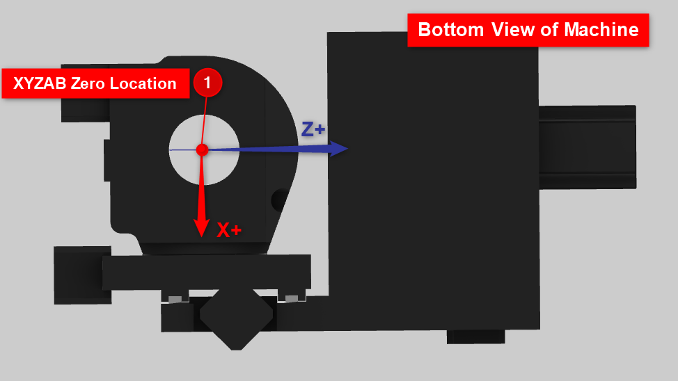
Pic. 5 – Bottom View of the Machine
Pic 5, shows another view if you were looking underneath the machine upward. In this picture, simply observe that the XYZAB Zero origin location is directly in the center of the B rotation axis.
Setting up the Machine Coordinate System for BobCAM
Now that you understand the Machine XYZAB Zero position on the machine, it’s time to set up this same location on your part inside of BobCAD-CAM.
In the simplest sense, take another look at picture 1 in this document. The Machine Coordinate System (that is defined on the “Machine Setup” page) in the software should be oriented and positioned in the exact same way as we see in picture 1 (the Machine Zero).
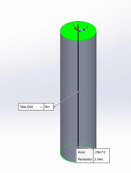
Pic. 6 – 1 Inch Diameter, 4-Inch long Stock
Let’s say that we have a 1 Inch Diameter, 4-Inch Long piece of stock that we want to use for the job. (See pic. 6)
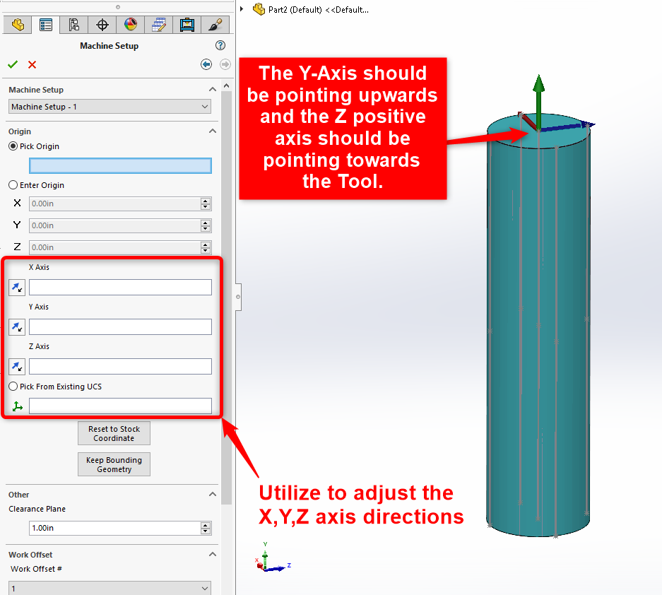
Pic. 7 – Orient the X,Y,Z Axis directions in the “Machine Setup” page
When initially setting up the CAM job, after you created the stock for the job, the Machine Coordinate System for the job is set up on the next page called, “Machine Setup”. (See Pic. 7)
The first step is to orient your X,Y, and Z axis so that it makes sense for your machine. You can utilize the X, Y, Z Axis directions and Existing UCS buttons to adjust the directions of the Axes. The Pocket NC 5 Axis Mill machine is a 5-Axis Horizontal style Mill CNC Machine. This means that the Z-Axis is oriented horizontally (which is different from most machines where the Z-axis is vertical.) Since this is a Horizontal machine, your Y-Axis should face upwards and the Z-Axis is Horizontal. The positive Z-Axis should be pointing towards the spindle of the machine which is pointing to the right in Pic. 7. Picture 7 above shows the correct orientation of the X,Y, and Z Axis for this machine.
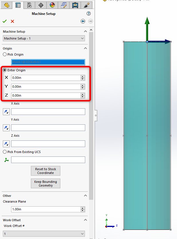
Pic. 8 – Enable “Enter Origin”
Finally, we need to adjust the Y-Axis amount to align it with the Machine XYZ Zero position. To do this, start by enabling “Enter Origin” (See Pic. 8)
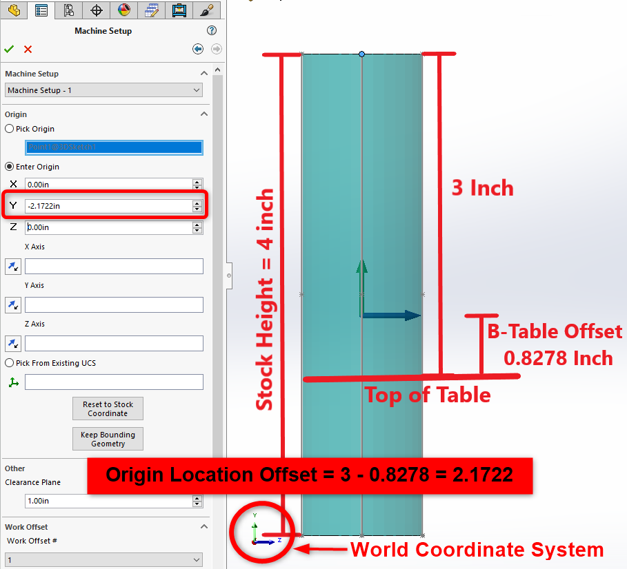
Pic. 9 – Calculating and Setting Origin Location Offset
Now, we need to utilize the X, Y and Z boxes to adjust the position of the Machine Coordinate System. In our example, our stock is 4 inches long and the stock will stick out of the table by 3 inches exactly.
Note: Make sure you measure this distance on the machine to get a more accurate distance. This will especially matter if you plan on doing 5-Axis movement on the machine. If this value is incorrect, the tool will not be properly compensated and will be shifted to the wrong location.
Given this information and the Measured B-Table Offset given by your machine manufacturer (see Pic. 3), we can find the Origin Location Offset value.
If we reference the top of the stock, this value would be 3 inches – B-Table Offset (0.8278) = 2.1722 inches. To determine which axis we should use, reference the World Coordinate System at the bottom left of your graphics area. In our example, to move the Origin Location Offset, we need to move in the negative Y direction. So, we will enter -2.1722 inches in the Y box.
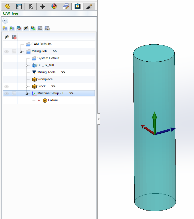
Pic. 10 - New Job set up with correct Machine Coordinate System
You can now hit the green checkmark button and you have now completed the “Machine Setup” page and finished the Job Setup. If you ever want to view your Machine Coordinate System again, simply click on “Machine Setup – 1” to view it in the graphics area. (See Pic. 10)
If you need further assistance, please contact our support team at (727) 489 – 0003 or [email protected]