Knowledge Base Articles
- BobCAD-CAM V36
- Getting Setup
- Quick Tips & Tricks
- The BobCAD Basics
- Advanced Topics
- Computer Issues
- NC Editor
- Post Processor
- Our Forum
Chamfer Toolpath (Selecting Geometry)
This article will show you how to select the correct geometry for the Chamfer Toolpath with sharp edges or 3d chamfered edges of your model.
If you are having trouble with selecting 3D Chamfers, please make sure you are selecting the Bottom Edges of the Chamfer (See. 3D Chamfer (Geometry Selection) below).
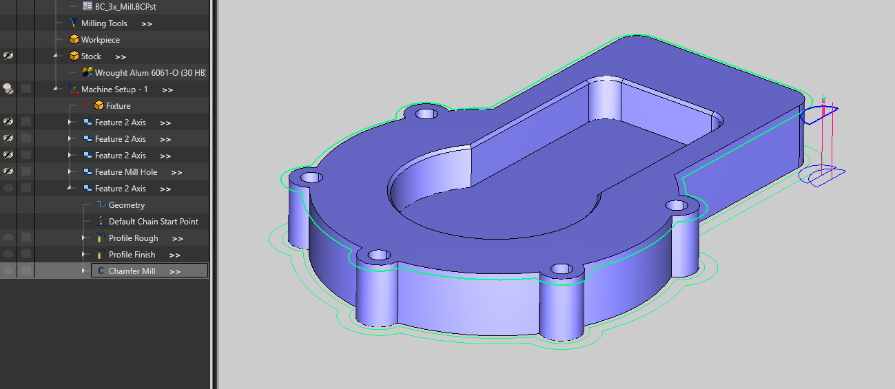
Below is a step-by-step guide for setting up a Chamfer Mill Toolpath. You will see an example of a Sharp Edge Model and a 3D Chamfer Model. In both cases, we want to add a Chamfer toolpath to chamfer both areas.
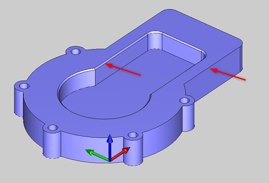
Pic. 1 – Example Part with a 3D Chamfer and Sharp Edge
General Workflow (using Sharp Corners / Wireframe)
If you have a Sharp Corner on your model and you just have the 2D wireframe of the model (See Pic. 2), this section will show you how to properly select your geometry for the Chamfer Mill Toolpath Operation.
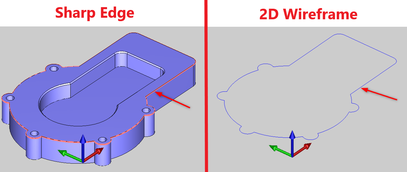
Pic. 2 – Sharp Edge and 2D Wireframe Geometry for Chamfer Toolpath
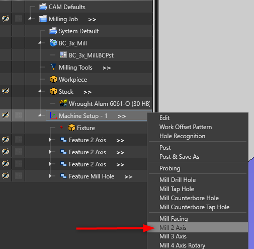
1. To create a Chamfer Toolpath Operation, go to your CAM Tree, Right-click on “Machine Setup – 1” and select “Mill 2 Axis”. Click “Select Geometry” in the Feature Wizard.
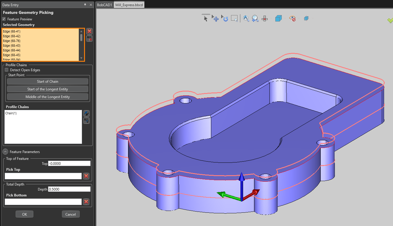
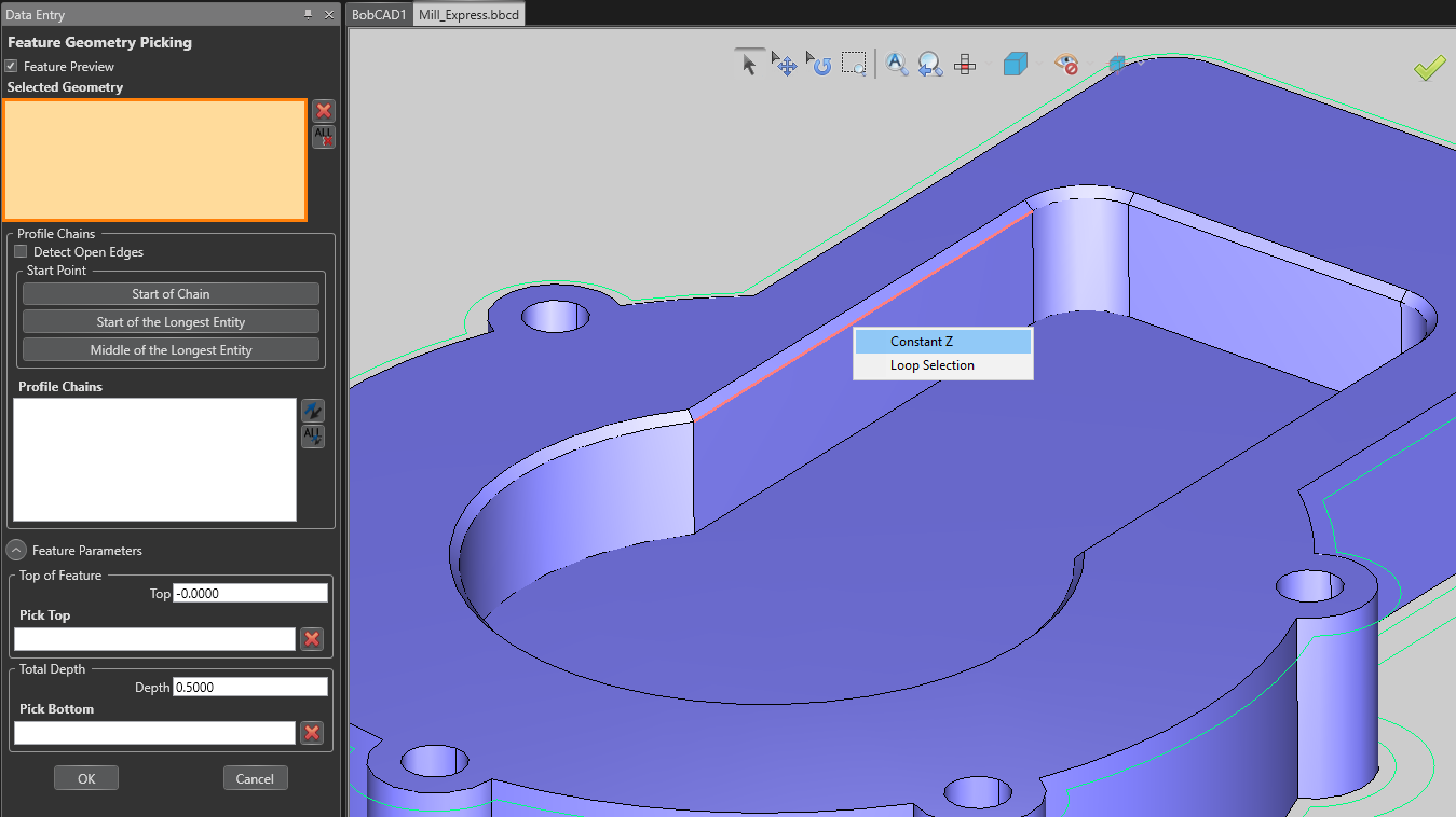
2. You will see that “Selected Geometry” is highlighted in Orange which indicates that it is active and ready to select geometry for the Feature.
a. For Sharp Geometry – Right-click on a Sharp Edge of the model and select “Constant Z”
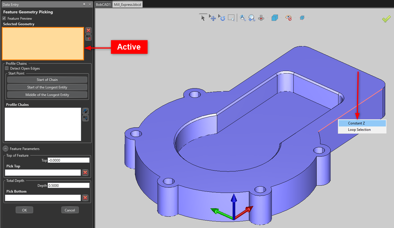
b. For Wireframe Geometry – Chain select the geometry by holding SHIFT + Left-Click on the goemetry
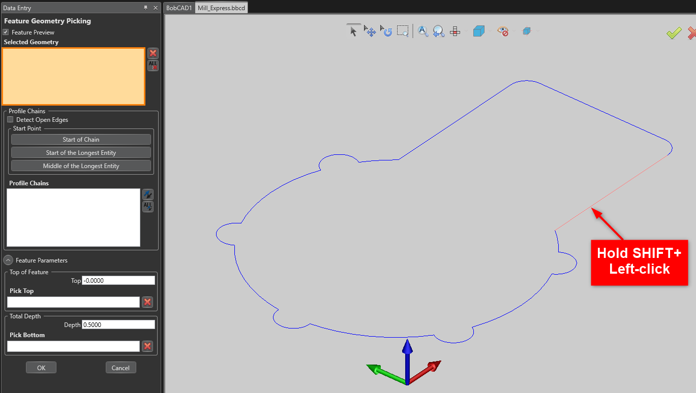
Once you have selected your geometry, you can now adjust your “Profile Chains” to decide where to start your toolpath and which direction it will travel (CW | CCW) (See pic below). You can also adjust your Top of Feature and Total Depth here. However, for the Chamfer Toolpath, you will set your own Chamfer Depth inside the feature.
The Total Depth here will be used if you also want to add a Profile Finish, for instance, to also profile the outer profile of the model with an Endmill Tool. Since BobCAD-Cam is feature-based, you are able to have multiple Toolpath Operations in one feature. This allows you to setup multiple toolpaths all at once and compute them all at the same time.
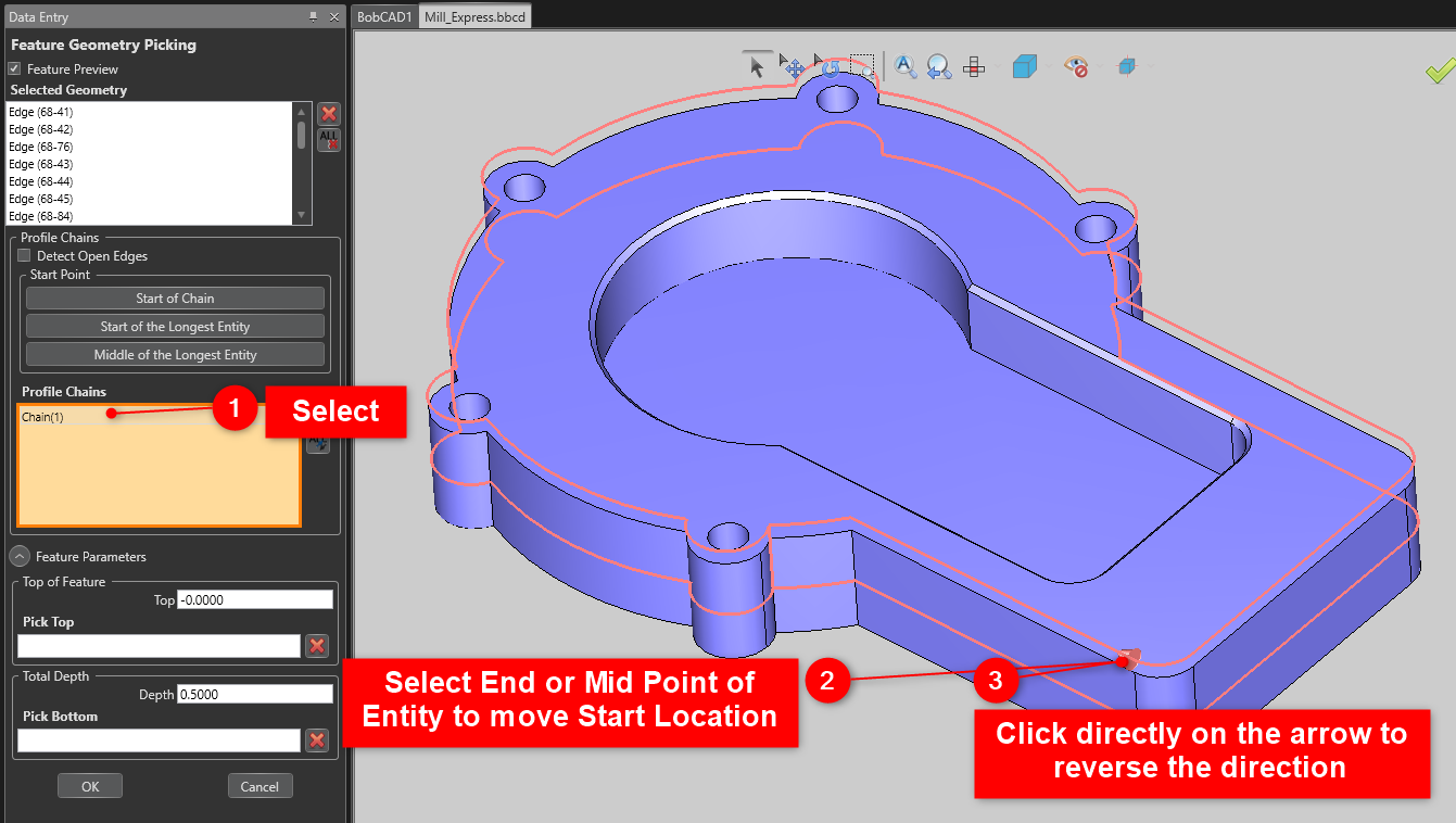
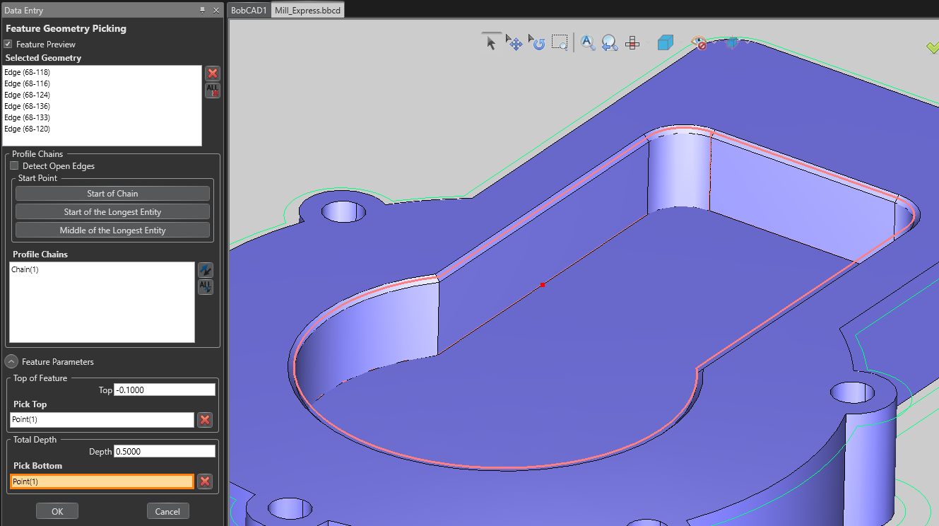
3. Click inside the “Profile Chains” box to make it active, click an endpoint or midpoint of the geometry to set a start point location, and click directly on the arrow to set the direction of the cut.
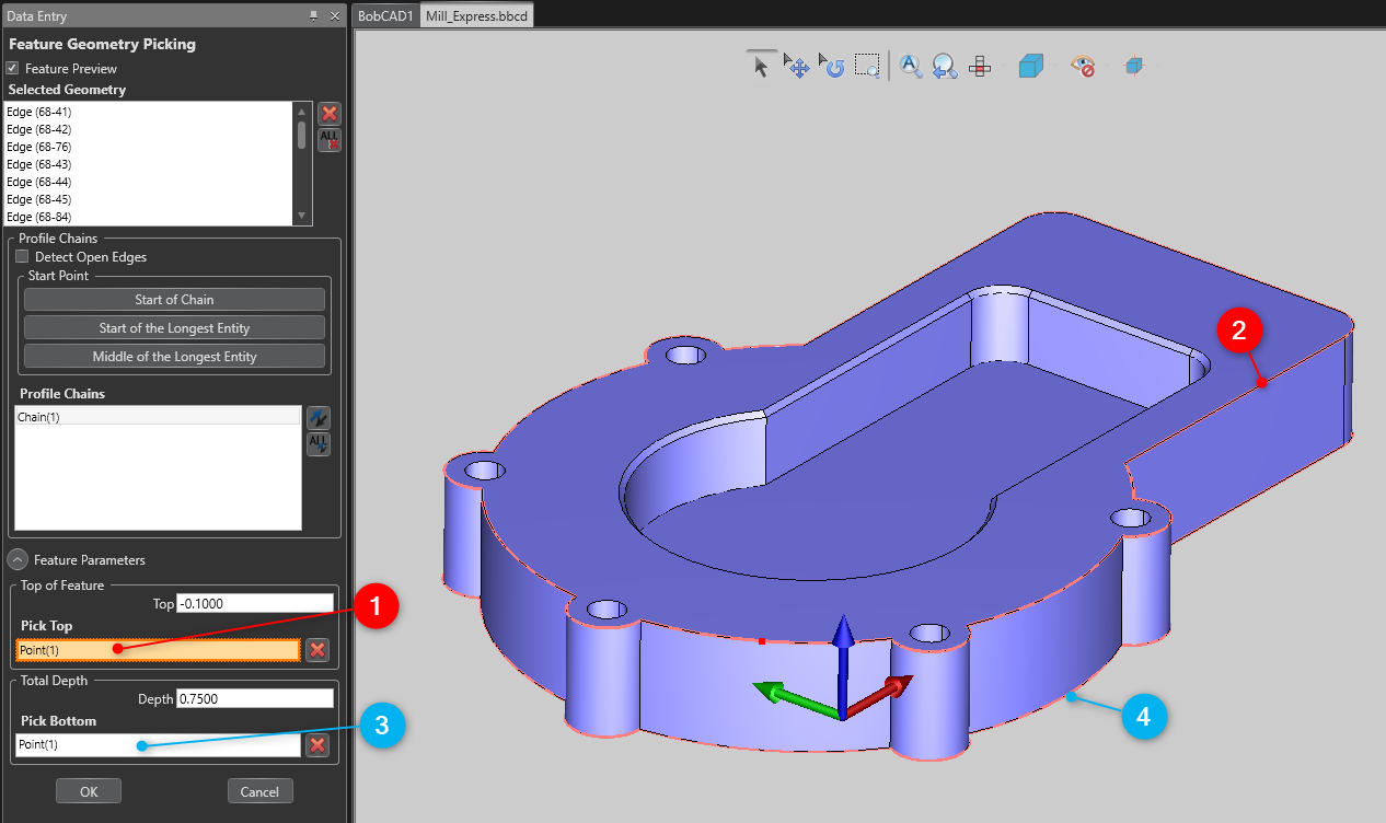
4. You can set up your Top of Feature and Total Depth in the “Feature Parameters” section. Type in the values manually if you know them, or click “Pick Top” “Pick Bottom” to select them on the model. Click “OK” when done.
Note: The Total Depth is correlated to the whole feature for all operations. There will be a separate field for Chamfer Depth in the Feature Wizard.
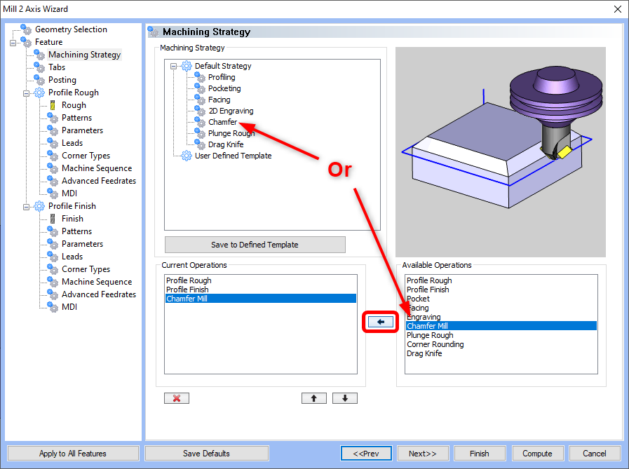
5. Hit “Next” at the bottom of the Feature Wizard until you get to the “Machining Strategy” page. You can either select “Chamfer” from the Default Strategy list if you just want the chamfer by itself. Or, you can add the “Chamfer Mill” Operation to the Current Operations by selecting it and hitting the Right Arrow button. Hit “Next”.
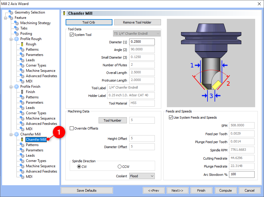
6. To jump straight to the Chamfer Mill Operation, just click directly on the second “Chamfer Mill” in the left-hand column. You can now define your Chamfer Mill Tool on this page.
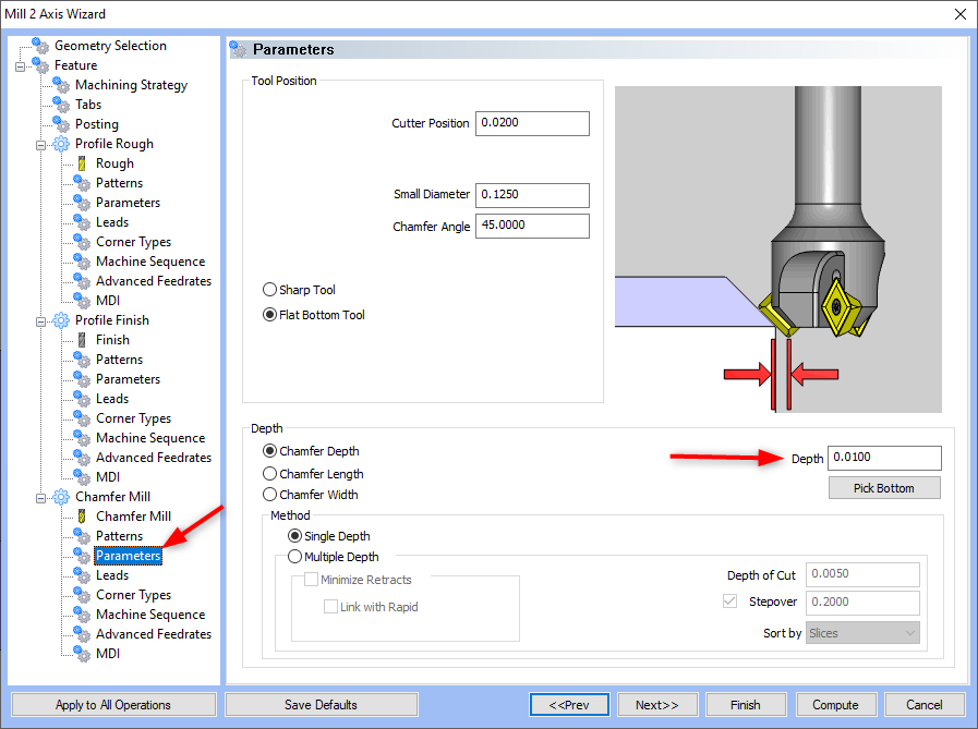
7. To define your Depth, go to the “Parameters” page. There are multiple different ways to define Depth. Pick which method is easiest for your application.
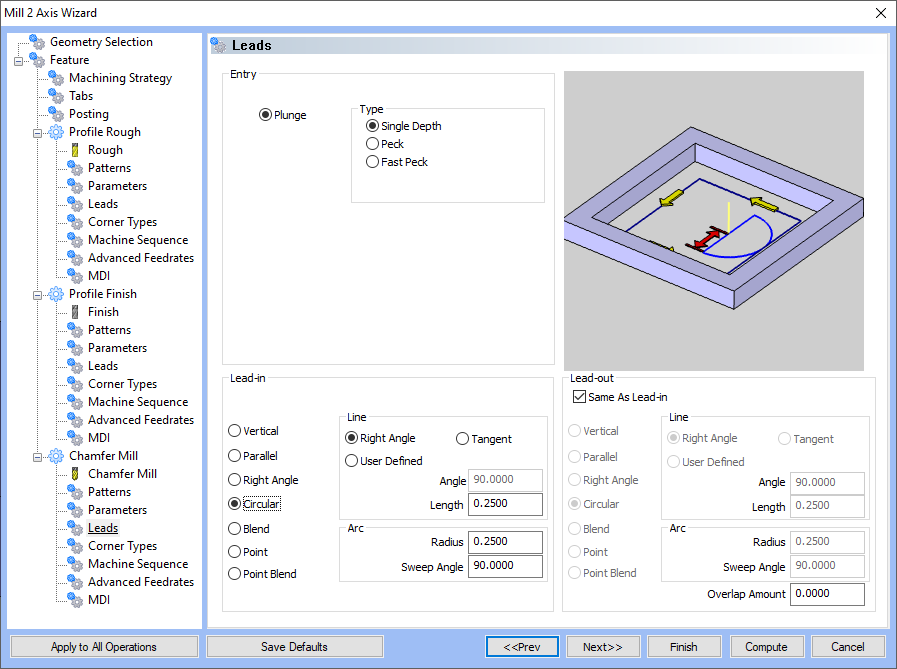
8. Hit “Next” or click directly on “Leads” to get to the “Leads” page. Here you can setup a Leadin/out If necessary.
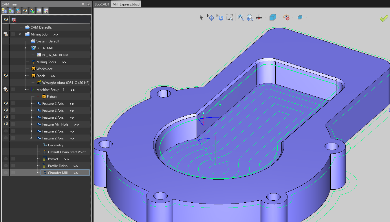
9. Change any other parameters needed and press “Compute” when finished. You will now see the two Profile Toolpaths in this example along with the correct Chamfer Depth for the Chamfer Toolpath as well.
3D Chamfer (Geometry Selection)
The Workflow for the 3D Chamfer is the same as the general workflow seen in the last section. The difference is what geometry you need to select.
1. When you get to the Geometry Selection page (Step 2 in Previous section), MAKE SURE that you select the bottom edge of the chamfer. Otherwise, the Toolpath will not be properly compensated when creating the toolpath.
2. Selecting the geometry correctly will also allow you to use other operations in the Feature Wizard as well as you will have the correct geometry selected, for a Pocket Operation in this example.
3. After setting up a Pocket, Profile Finish and Chamfer Mill in the Feature Wizard and defining my Chamfer Depth on the “Parameters” (like we did in Step 7 above), Compute the toolpath.
If you need further assistance, please contact our support team at (727) 489 – 0003 or [email protected]