Knowledge Base Articles
- BobCAD-CAM V36
- Getting Setup
- Quick Tips & Tricks
- The BobCAD Basics
- Advanced Topics
- Computer Issues
- NC Editor
- Post Processor
- Our Forum
Creating a Solid Model from Surfaces
This document will describe how to create surfaces from a wireframe. Then, create a solid model using those surfaces. Turning surfaces into a solid model can be useful for many different reasons. If you want to use the Boolean Add/Subtract functions, create a Solid Chamfer/Fillet on the model or any of the other create 3D functions that can modify the model. You also might just want to load the 3D model into another software, like a splicing software for a 3D printer.
There are many different ways to create surfaces inside of BobCAD, but the concept for creating a solid from surfaces is the same. Just follow the example below to understand this concept:
Step By Step:
1. Create a wireframe of the model using the Create 2D tab
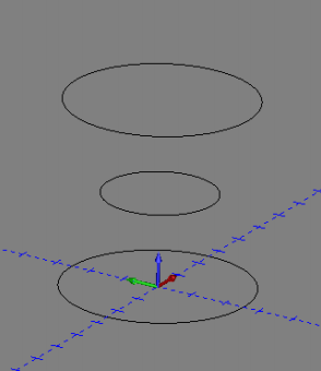
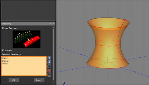
2. Go to the Create 3D tab and select Cross Section in the Surfaces section.
3. Create a chain with each circle. Hold SHIFT + Left Click in the same location on each circle. (Make sure all chains are facing the same direction.)
4. Click OK then Cancel
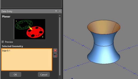
5. Click Planar in the Create 3D tab in the Surfaces section
6. Select the top edge of the model as your geometry.
7. Click OK then Cancel
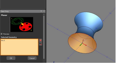
8. Repeat steps 5-7 for the bottom edge of the model.
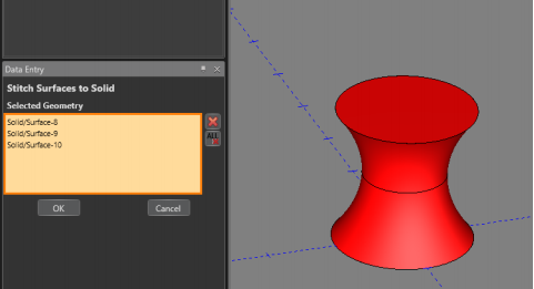
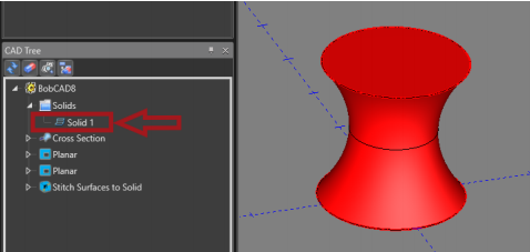
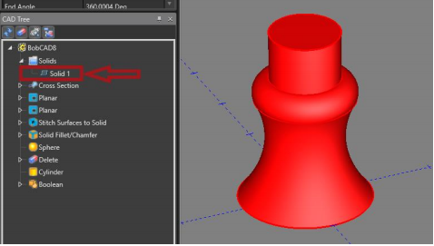
9. In the Create 3D tab, select Stitch Surfaces to Solid in the Modify section
10. Select all three surfaces created and click OK then Cancel
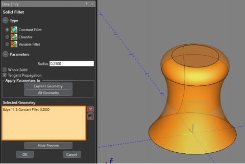
11. In the Create 3D tab, select Solid Fillet
12. Type in the desired radius and click on the outer top edge of the model
13. Click OK then Cancel
14. In the Create 3D tab, click Cylinder and create a cylinder that intersects the model
15. Click OK then Cancel to complete the cylinder
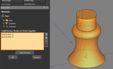
16. In the Create 3D tab, select Boolean Add
17. Select both solids and click OK then Cancel
18. Create a new layer in the layers window and name it “Spun Profile” and make sure there is a green check box next to it
19. Go to “Create 2D” Tab
If you need further assistance, please contact our support team at (727) 489 – 0003 or [email protected]