Knowledge Base Articles
- BobCAD-CAM V36
- Getting Setup
- Quick Tips & Tricks
- The BobCAD Basics
- Advanced Topics
- Computer Issues
- NC Editor
- Post Processor
- Our Forum
Work Coordinate System Vs. CAD Coordinate System
This article contains a large overview of the differences between the CAD and Work Coordinate Systems. For some users, there is a common misconception that the CAD Coordinate System is the same thing as the Work Coordinate System. However, this is not the case. These two Coordinate Systems serve two entirely different functions in the software and this article will explain in detail the differences between them.
Simply put, the main difference between CAD and Work Coordinates is that the CAD Coordinate System is used whenever creating or modifying geometry in the software. TheWork Coordinate System is used when creating toolpath in the CAM Job and when posting out the G-Code for the job. The G-Code references the Work Coordinate System. So, it is clear to see that it is very important to understand the differences and to know how to modify these coordinate systems according to your program specifications.
Where Can I Find These Coordinate Systems?
Locate CAD Coordinate System
The CAD Coordinate System can be found by default in the Graphics Area of the software (See Pic 1). This Coordinate system is also referred to as the “UCS” or User Coordinate System and can be located by showing the “UCS” window in the software.
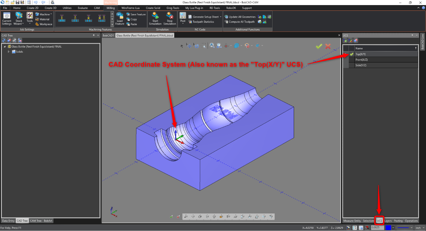
Pic 1 – CAD Coordinate System, Also Known as “Top(X/Y)” UCS
This UCS Gnomon shows the X, Y and Z Axes arrows denoted by the colors Red, Green and Blue respectively
Note: If Turning Mode is enabled on the “Home” tab, that would make X Green, Y Blue and Z Red. This allows for an XZ plane when viewing the Top(X/Y) UCS.
This Gnomon along with its’ Axes Ticks Marks can be hidden by going to File > Settings > Current Document > Display and unchecking “Show Axis” and “Show Gnomon”. Then, hit “Apply” and “OK”. (To default this setting, go to File > Settings > Document Default > Display and uncheck them there.)
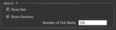
Pic 2 – Settings > Display > Axis X – Y, Show or Hide Axis and Gnomon
You can also create your own user-defined UCS by navigating to the “UCS” window and selecting the “Create New UCS” (Plus) icon at the top left.
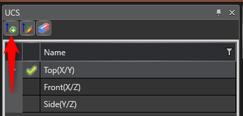
Pic 3 – Create New UCS icon in “UCS” window
Locate Work Coordinate System
The Work Coordinate System can be found by navigating to the CAM Tree and clicking on any of the Machine Setups that you have in your Job.
Note: The CAD Coordinate System will still be visible. The Work Coordinate System will be larger in size than the CAD Coordinate System.
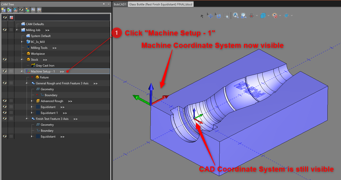
Pic 4 – Show the Machine Coordinate System
This Coordinate system is defined on the “Machine Setup” page when you initially created the job. To access this Machine Setup page again, right-click on “Machine Setup – 1” (In reference to pic 4) and select “Edit” (see pic 5).
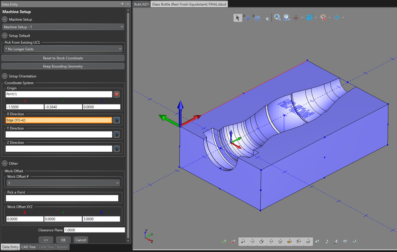
Pic 5 – Machine Setup Page
To redefine the Work Coordinate, utilize the Origin, X, Y and Z Direction boxes. Adjust the location of the coordinate system and define the direction of the axes.
Note: When defining the Axis Directions, you can select a line that is parallel to the direction of that axis if you do not have a line on the Origin location. Or, select a point and the axis will point directly toward that point.
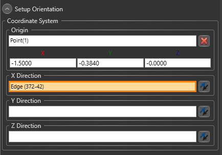
Pic 6 – Coordinate System box to define the Work Coordinate System
When finished, press “OK” at the bottom of the window. If you have already created toolpath, you will notice that the toolpath shifts. ALWAYS make sure to “Update All Geometries” and “Compute All Toolpath” in the “Milling” tab after you have modified the Machine Setup to recalculate the toolpath in the new X,Y,Z locates.
When are the Coordinate Systems Used?
A common question you may have is: When is the CAD and Work Coordinate Systems used / referenced inside the software?
Reference CAD Coordinate System
The CAD Coordinate System is used when creating or modifying any geometry in the software. For Example, creating a line from the “Create 2D” tab. Or, using the “Translate” function from the “Utilities” tab (See pic 7)
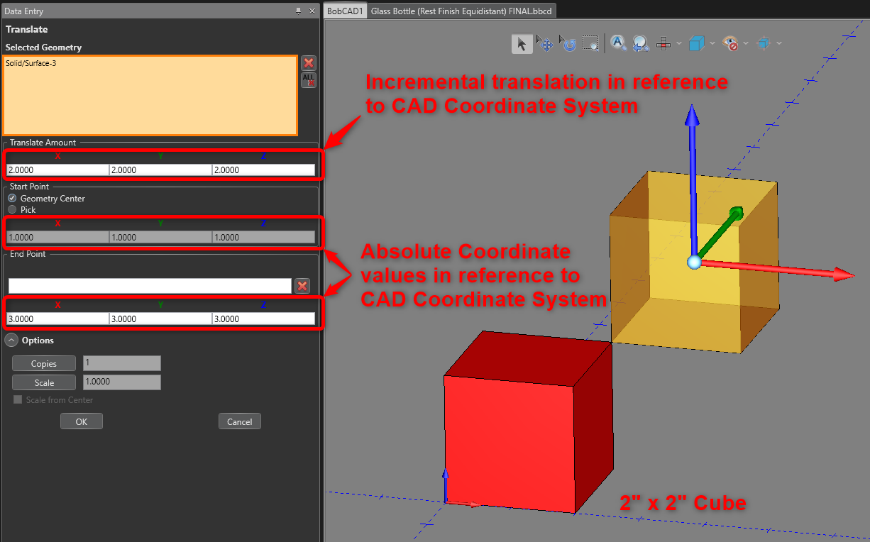
Pic 7 – Translate Function showing X, Y, Z values in reference to the CAD Coordinate System
Pic 7, shows a 2” by 2” cube. You can observe that all the X, Y, Z values are in reference to our CAD Coordinate System. The “Translate Amount” is an incremental translation in reference to the CAD Coordinate System. The other X, Y, Z values in the Start and End Point boxes are absolute values based on the position of the Start and End points in reference to the CAD Coordinate System. Since the Start Point is in the center of the cube (located at 1,1,1) and the Translate amount moves in the X by 3, Y by 3, and Z by 3, this places the preview of the cube in the far top right corner of the cube when looking at pic 7.
Important!
There is a common confusion with how to setup and define a CAM Job using the X,Y,Z coordinates. The CAD Coordinate System is also utilized when initially setting up a CAM Job. The CAD Coordinate System is used to set up the initial CAM Job and create the Work Coordinate System. So, the X, Y, Z values you see on the “Stock Definition” and “Machine Setup” are in reference to and derived from the CAD Coordinate System.
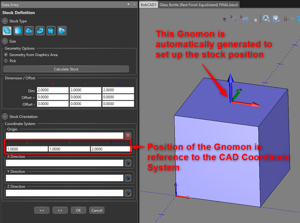
Pic 8 – Stock Definition Page showing Stock Gnomon in reference to CAD Coordinate System
Let’s take that same cube and create a new CAM Job. When we get to the “Stock Definition” page in Pic 8, we can observe a couple of things. First, observe that there is now a new Gnomon that shows up. Users will often confuse this Gnomon as the Work Coordinate System. However, the Work Coordinate System does not get defined until the next “Machine Setup” page.
The new Gnomon that you see on the “Stock Definition” page allows you can set up the Stock Orientation for this CAM job. It is simply used to adjust the Stock that gets created to align with our CAD Model.
You can utilize the “Stock Orientation” section on this page to move and realign the Stock to the CAD Model. In most cases, there is no need to adjust this “Stock Orientation” because the CAD Model is already aligned to our CAD Coordinate System. However, in cases where the part may have been part of an assembly file, the part is more than likely not to be in alignment with the CAD Coordinate System and you can utilize this “Stock Orientation” section to adjust the stock.
You can also observe that the X, Y, Z values that show up under “Stock Orientation” are in reference to the Cad Coordinate System. This is a 2” x 2” cube. So, the new Gnomon that gets created for the Stock position is located at the top center of the Cube or at 1,1,2 with respect to the CAD Coordinate System.
Important Note: The important thing to note here is that the Work Coordinate System is not defined here and the X, Y, Z values that you do see are in reference to CAD coordinate system. This new Gnomon is only utilized to move and realign the Stock to the CAD Model.
Similar to the “Stock Definition” page, the X, Y, Z values under the “Origin” box that you see on the “Machine Setup” page are also in reference to the CAD Coordinate System (See pic 9).
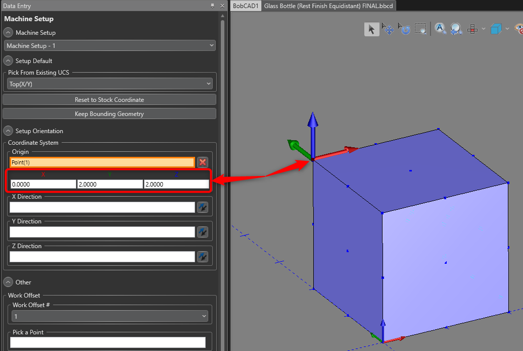
Pic 9 – X, Y, Z values in the Coordinate System box on the “Machine Setup” page in reference to the CAD Coordinate System
Reference Work Coordinate System
The Work Coordinate System is used for the CAM Jobs. This includes the creation of toolpath and most importantly the G-Codes that get posted out in the NC file for the job.
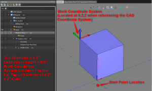
Pic 10 – Example Work Coordinate System
In Pic 10, the Work Coordinate System is located in the Far Top Left Corner of the 2” by 2” Cube. The NC file that gets posted out for this job will be in reference to that location. NOT the location of the CAD Coordinate System (located at the near bottom left corner of the Cube).
To test your comprehension of the Work Coordinate System, see if you can find what the X, Y Start Point Location should post out as in Pic 10.
Question: When posting out the G-Code (In pic 10), what will be the X, Y Start Point Location that shows up in the NC file?
Given that we have a 2x2x2 Cube and the Machine Setup Location is located at the far top left corner of that cube. A Tool Diameter of 0.5” is being compensated in the toolpath and there is a parallel leadin of 0.3” that goes along the Y Axis.
To find the X, Y Start Point Location, we can break the process down into 2 steps. Find the X value. Then, find the Y value. The most important element of this is understanding how the X and Y values are referenced in the Graphic Area of the software.
To find the X value, you can view the part from a Front perspective. If we look at Pic 10 and 11, we can see that the Start Point location in the X direction only needs to account for the Radius of Tool. The Work Coordinate System is on the left side of the part and the Leadin is not applied in the X direction.
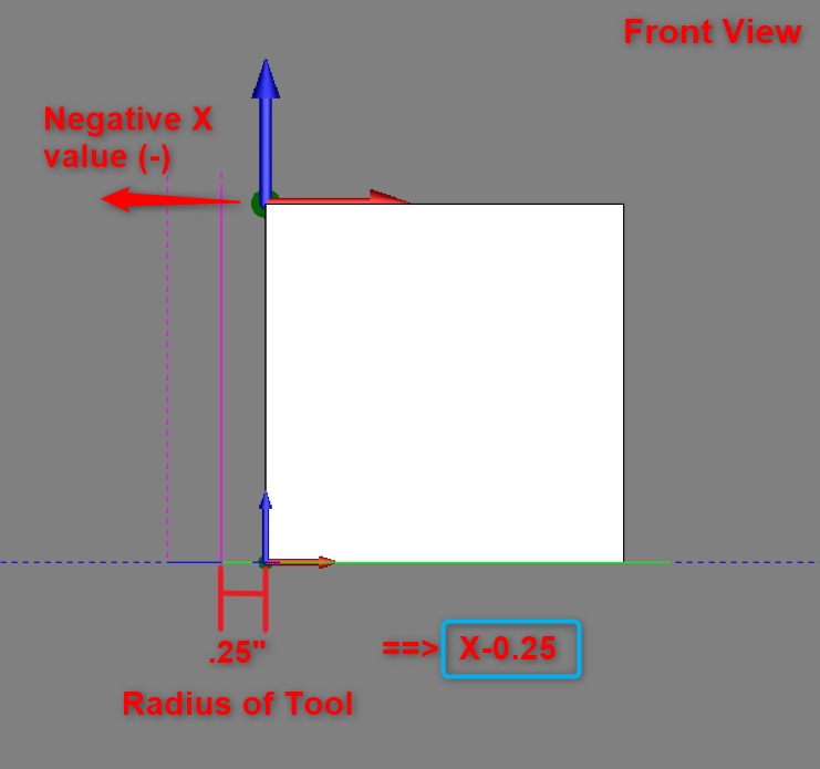
Pic 11 – Front View of Part, X Start Point Value
Since the X axis is pointing to the right and the Start Point Location is on the left side of the Y axis, the output will be a negative value. The tool radius is 0.25.
So, our expected output would be X-0.25
Now, let’s think about the Y value. Pic 12, shows a side view of the part. In this view, you can see that we need to account for 3 variables now. The Work Coordinate System is located in the Top Left of the part. We are also on the negative side of the Y axis. So, the output should also be negative.
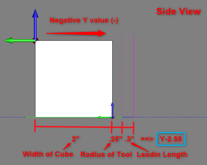
Pic 12 – Side View of Part, Y Start Point Value
We need to add the width of the Cube, the radius of the tool and the Leadin length. In other words, Y = - (2 + 0.25 + 0.3)
So, the expected output is Y-2.55
Answer:
The G-code output for the X, Y Start Point Location that shows up in the NC file is;
X-0.25 Y-2.55
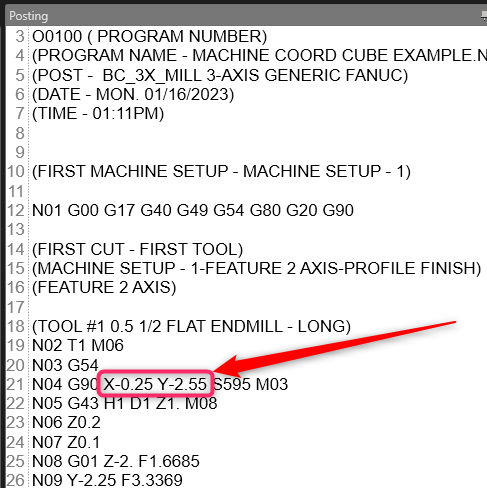
Pic 13 – X, Y Start Point Position G-Code Output
Summary
Overall, understanding the differences between the CAD and Work Coordinate Systems is an important distinction to understand. This article provides a good overview of what each Coordinate is, where you can find them in the software and how they are referenced throughout the software.
This should give you a good fundamental understanding that you can utilize in your own CAD models and CAM jobs.
If you need further assistance, please contact our support team at (727) 489 – 0003 or [email protected]