Knowledge Base Articles
- BobCAD-CAM V36
- Getting Setup
- Quick Tips & Tricks
- The BobCAD Basics
- Advanced Topics
- Computer Issues
- NC Editor
- Post Processor
- Our Forum
How to Use Work Offset Patterns
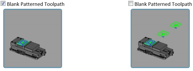
BobCAD-CAM now allows you to output copies of entire machine setups, and allows you to specify different work offsets for each copy. While Toolpath Patterns have been offered in the past, and could be applied to Machine Setups, there was no way to output the same code with different work offsets. This could be a little frustrating when machining the same job on multiple locations on the table, because it meant you'd need to manually copy and paste the output, then adjust the work offset number on each copy by hand. Now, it's easy to create a Work Offset Pattern, set the work offset number to use, set the machining order, and even set a pattern type with distances so you can see how it would appear in simulation. The Work Offset Patterns allow you to view the toolpath in the graphics area, and to pattern the stock, fixtures, and workpiece in the simulation:
Step-by-Step
1. Go through programming the initial G54 part until it is complete.
2. Once the initial part has been completely programmed then right click onto the machine setup in the CAM tree and click on “Work Offset Patterns”.
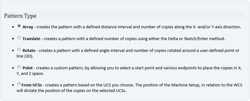
3. Select one of the five work offset patterns which are: array, translate, rotate, points, from UCS.
4. Fill out the Pattern Parameters section and the number of copies to tell the Work Offset Pattern how far apart each work offset is compared to the original for simulation and how many Work Offsets that BobCAD should be creating.
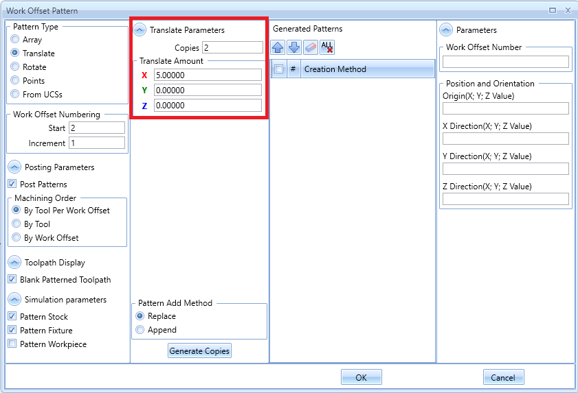
Note: The distance between each Work Offset in BobCAD does not make a difference in the G-Code as the actual location will be manually touched off in the machine.
5. Step Five: Hit the Generate Copies and hit OK, at this point if the user hits Post they will see the additional work offsets in the code.
If you need further assistance, please contact our support team at (727) 489 – 0003 or [email protected]