Knowledge Base Articles
- BobCAD-CAM V36
- Getting Setup
- Quick Tips & Tricks
- The BobCAD Basics
- Advanced Topics
- Computer Issues
- NC Editor
- Post Processor
- Our Forum
Creating Multiple Machine Setups Example
Introduction
The Machine Setup in the CAM Tree is used to define each setup of the part on the machine. In this example, we create two Machine Setups and demonstrate their setup on the machine.
Break
Example
Break
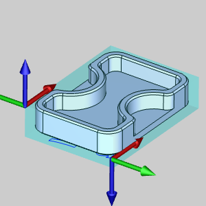
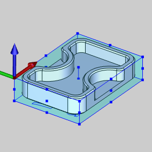
Part 1) Create Stock for the Part
The part used in this example is shown first. Once the part is oriented in the workspace, the stock can be created. Be aware that you do not need to orient the part in any special way. The stock and the machining origin are aligned to the part.
- When opening the Stock Wizard, rectangular stock is assigned to the part boundary by default.
Break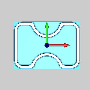
Break - We update the X and Y values.
BreakIn this case, X = 2.050 Y = 1.500.
Break 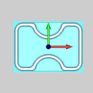
Break - After that, we move into a side view and update the Z value.
BreakIn this case, Z = 0.500.
Break 
Break - Now since we want to take a little off the face of the stock, and since our stock is currently flush with the part face, we update the Z value of the Stock Orientation Coordinate System by adding 0.0075 to it.
Break 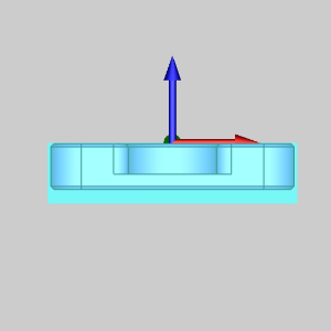
Break - Click Next to go to the Machine Setup.
Break
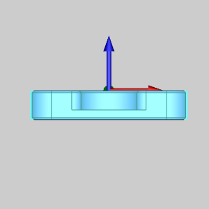
Part 2) Defining the First Machine Setup
- By default, boundary geometry is created based on the stock size.
BreakClick the desired, or near the desired, location of the Machine Setup.
Break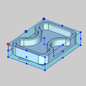
BreakThe Machine Setup snaps to the selected location.
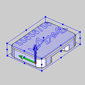
Break - In this case we have added 0.0075 inches to the top of our stock but we want to face the part to Z0, so we now lower the Z location by 0.0075.
Break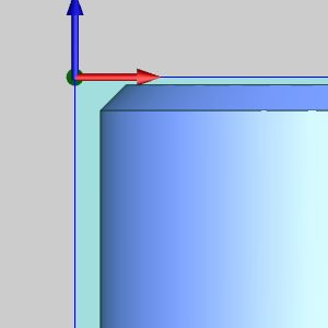
BreakBy doing this we can set depths in our features that make sense, and looking at the code output will be easier.
BreakOur pockets, for instance, are 0.25 inches. Had we left our Z0 to the top of stock, we would be setting a depth of 0.2575 and verifying that in the code as well.
Break
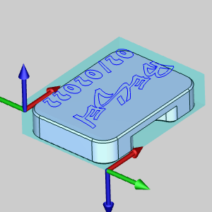
Part 3) Defining the Second Machine Setup
Once another Machine Setup is added to the CAM Tree, we can define it in the Machine Setup dialog as well. In this case we will be machining the first side, flipping the part around the X axis, and setting the machine setup in the same basic area as seen below.
Break
- Rotate the view in the graphics area around the X Axis as much as possible.
Break - In the Machine Setup, the bounding geometry once again appears.
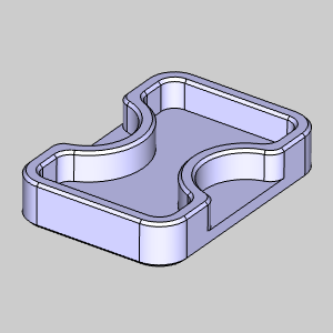
Break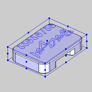
BreakHowever, by the time we get to the second Machine Setup on the machine, our stock will look more like this:
Break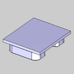
BreakWe set our Machine Setup based on the cut part, and not the original stock in order to eliminate any possible variations between setups.
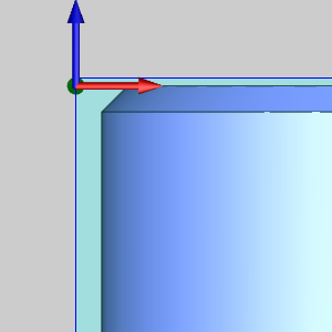
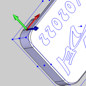
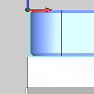
BreakSet the origin against the first face of the part.
Break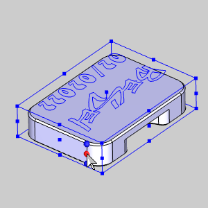
BreakTake note of the X Axis location, as this will be the value we use.
Break - Set the origin against the second face of the part.
Break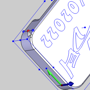
BreakNow, take note of the Y Axis location.
Break - Set the origin on the top edge of the chamfer.
Break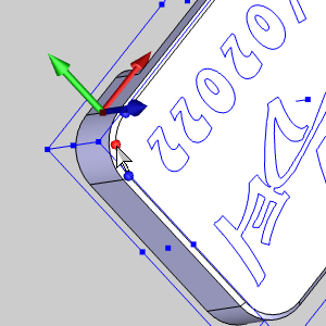
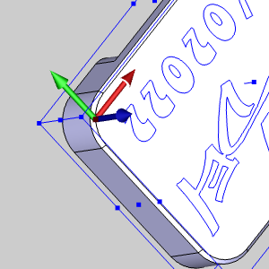
Break - Finally, update the X and Y values you took note of previously.
Break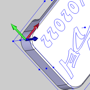
BreakThis is where we want our second setup.
Break
Part 4) Setting up on the Machine: Machine Setup 1
- Prior to setting up on the machine, we have chosen spacers of a precise height that will lift our part just high enough for the final profile cut to reach depth without touching our vise.
Break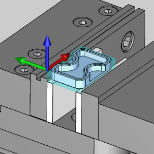
Break - Although we are going to be touching off on the stock itself, we move the stock flush with the sides of the vise, as we will do with our second setup for consistency.
Break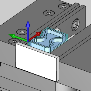
BreakThis can be done by placing another spacer firmly against the side of the vise, and moving the stock against it before tightening the vise.
Break - Then, with the tool set, we touch off on the stock to set our work offsets.
Break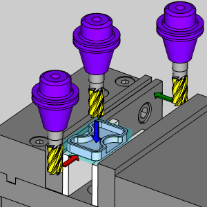
Break- Move the tool into position to find the X location, touch stock and note the X Axis location on the machine. This value + half the tool diameter will be the X value of our setup.
Break - Move the tool into position to find the Y location, touch stock and note the Y Axis location on the machine. This value + half the tool diameter will be the Y value of our setup.
Break - Move the tool into position to find the Z location, touch stock and note the Z Axis location on the machine. This value will be the Z value of our setup.
Break
- Move the tool into position to find the X location, touch stock and note the X Axis location on the machine. This value + half the tool diameter will be the X value of our setup.
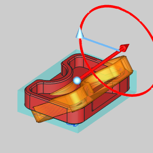
Part 5) Setting up on the Machine: Machine Setup 2
- Using the same spacers, and moving the cut portion of our stock flush with the sides of the vise, we are ready to touch off .
Break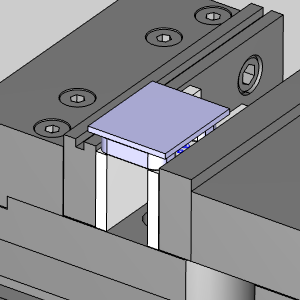
BreakNote in the image below, our total stock, shown in red, overhangs the jaws, shown in yellow.
Break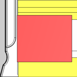
Break - Although we can't touch off on the stock itself because of this overhang, we utilize the vise, and the known height of our spacers to accomplish our task.
Break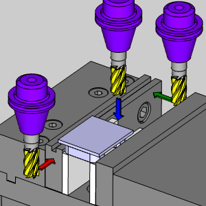
Break- Move the tool into position to find the X location against the vise jaw, touch jaw and note the X Axis location on the machine. This value + half the tool diameter will be the X value of our setup.
Break - Move the tool into position to find the Y location against the inside of the vise jaw, touch jaw and note the Y Axis location on the machine. This value + half the tool diameter will be the Y value of our setup.
Break - Move the tool into position to find the Z location against the top of our spacer, touch spacer and note the Z Axis location on the machine. This value + the height of our final part, 0.375 in this case, will be the Z value of our setup.
Break
- Move the tool into position to find the X location against the vise jaw, touch jaw and note the X Axis location on the machine. This value + half the tool diameter will be the X value of our setup.
This concludes the example.
If you need further assistance, please contact our support team at (727) 489 – 0003 or [email protected]