Knowledge Base Articles
- BobCAD-CAM V36
- Getting Setup
- Quick Tips & Tricks
- The BobCAD Basics
- Advanced Topics
- Computer Issues
- NC Editor
- Post Processor
- Our Forum
Using Layers
Break
Introduction
This topic will provide a basic explanation of what a Layer is, explain the Layer Manager, will show where to find the Layer Manager initially, and provide a link for the topic that shows how to relocate the Layer Manager.
Layers
The Layers are what CAD geometry is created on. The default CAD layer is always visible in the Layers Manager. While the original CAD layer, cannot be deleted, it can be renamed. Any geometry, or dimensions, that are created, are automatically placed on the Active layer.
The Layer Manager
The Layer Manager is located, by default, on the right side of the application. The location of the Layer Manager, however, can be adjusted to preference, as explained in the Introduction to Docking Panes topic. The purpose of the Layers Manager is to provide a way to keep your CAD drawings organized. Layers can be hidden to only show certain aspects of a drawing, or you can place different versions of the same part on separate layers. The Layers Manager can be used to specify a particular color and line style to use for each layer, and you can also select all the geometry on a given layer for use with other CAD functions or CAM features.
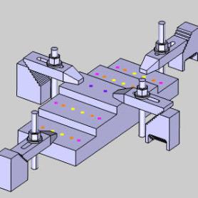
Example
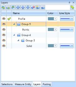
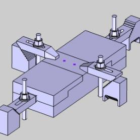
In this example we have a bunch of entities in the graphics area with only basic layer separation. We do have our points, profile, and solids separated by layer, but with group folders available, we can organize this much better to make any work we're doing a lot easier. In the graphics area, we currently we have:
- Profile
- Points for:
- Two different hole sizes
- One tap size
- One counterbore size
- Solids:
- Fixtures for:
- First job
- Second job
- Stock
- Workpiece
- Fixtures for:
We can use the same logic seen in these bullet points to build our layers and group folders!
Break
Part 1) Creating Groups and Layers
Break
- Click the Solid layer to highlight it, then click
 Move to New Group.
Break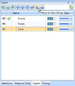
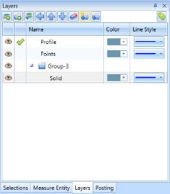
BreakThis creates the new group and places our Solid layer in it at the same time.
Break - Now click our new group and click Move to New Group again to place it in a group as well.
Break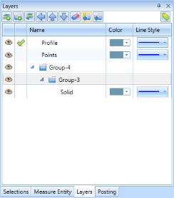
Break - Highlight our Points layer and click Move to New Group.
Break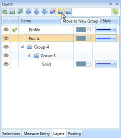
BreakNow that we have the groups we will need, we add the additional layers our entities will placed on.
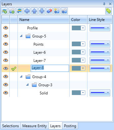
Break - With Group-5 highlighted, click
 New Layer.
Break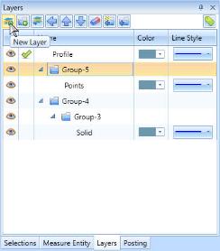
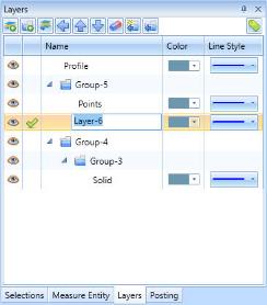
BreakLayer-6 is created inside Group-5. Notice the new names of the groups and layers are followed by the a number showing the total amount of layers/groups in the Layer Manager.
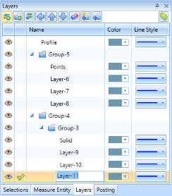
Break - Add three more layers to Group-5 to accommodate each hole type to be created for the part.
Break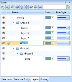
Break - Repeat this process to add three more layers to Group-3.
Break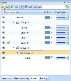
Break
Part 2) Renaming Groups and Layers
Although we could have been naming groups and layers as we went, once a name is changed, hitting enter automatically makes the next name editable. Because of this, you'll find it's much easier to create the group and layer structure you intend to use first, and then go back to name them all at once.
- Double-click our Profile layer to make the text editable.
Break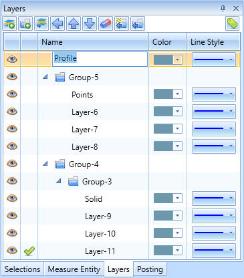
Break - Update the name to Profile Cut, and press Enter.
Break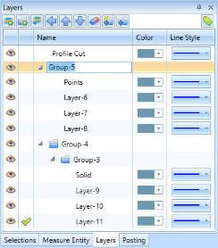
BreakThe group name becomes editable.
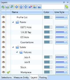
Break - Repeat this process to update each item to the following:
Break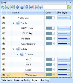
Break
- Profile Cut
- Points
- 0.875 Hole
- 1/4 20 Tap
- 0.5 Hole
- Counterbore
- Solids:
- Fixtures
- Job A
- Job B
- Stock
- Workpiece
Break
- Fixtures
Part 3) Moving Layers Between Groups
You might have noticed in creating our solid layers, all layers were placed inside the Fixtures folder. This was done to demonstrate the way to move layers.
- Drag and drop the Workpiece layer to the Solids group.
Break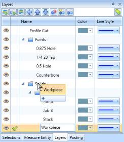

BreakNotice the layer is now outside the Fixtures folder.
Break - Click the Stock layer to highlight it and click
 Move Out.
Break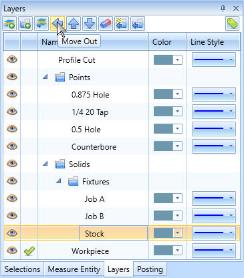
BreakThe Stock layer is moved out of the Fixtures group and is now located in the Solids group with our Workpiece layer.
Break - Right-click anywhere in the Layers manager and select Collapse All.
Break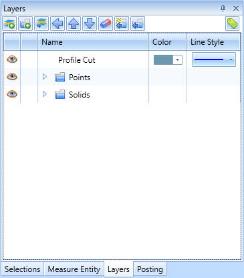
BreakAll groups and layers are created, organized, and can easily be collapsed.
Break - Right-click anywhere in the Layers manager and select Expand All.
Break
Break
Part 4) Moving Entities to Layers
Now that we have our layers created, and organized in groups, we can move the entities to the appropriate layers.
- Click in the Active Layer column of the Job A row to make it the active layer.
Break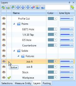

Break - Since the Profile Cut geometry is already on the correct layer, click
 to hide it.
Break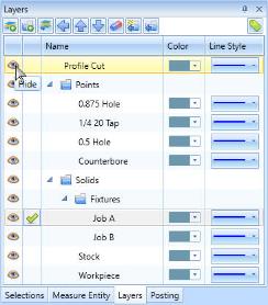
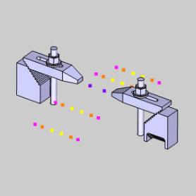
Break - Hide the Solids group.
Break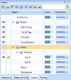
Break
- Set the Stock layer as the active layer.
Break - In the graphics area, turn on selection mode and select the geometry shown.
Break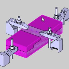
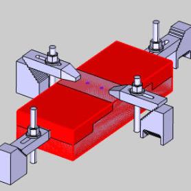
Break - With the Stock layer set to active, select
 Modify to Current Layer.
Break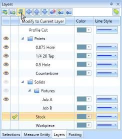
BreakThe stock is placed on the hidden layer and is no longer visible.
Break - Set the Workpiece layer as the active layer.
Break - Select the workpiece.
Break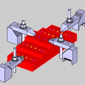
Break - With the Workpiece layer set to active, select Modify to Current Layer.
Break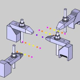
Break - Set Job B layer to active, choose the two further fixtures, and select Modify to Current Layer.
Break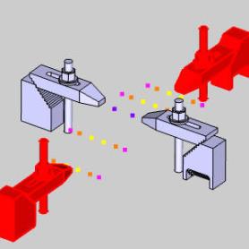
Break - Hide Job A layer.
Break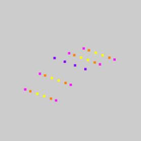
BreakSince this was the original Solid layer, this is where we were moving all the solids from.
Break
Part 5) Selection by Color
To make selection of multiple points a little easier, we will use the Pick By Color option in the Home ribbon.
Break
- Right-click the 0.875 Hole layer and select Show Only This Layer.
BreakAll other layers are now hidden.
Break - Set the 1/4 20 Tap layer to active.
Break - In the Quick Selection group of the Home ribbon, click
 Pick By Layer to see additional options and select
  Pick By Color.
BreakThe Select Colors dialog appears.
Break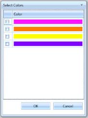
Break - Select Yellow, and click OK.
Break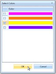
BreakThe Yellow points are all selected.
Break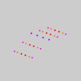
Break - In the Layers Manager, select Modify to Current Layer.
Break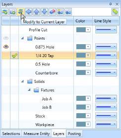
BreakThe Yellow points for our tapped holes are moved to the hidden 1/4 20 Tap layer.
Break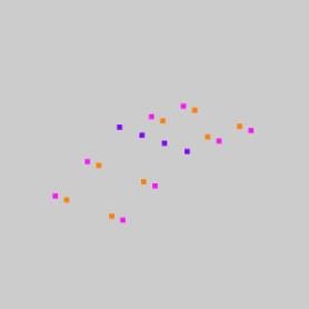
Break - Set the 0.5 Hole as the active layer.
Break - Select Pick By Color again.
BreakThe Select Colors dialog appears.
Break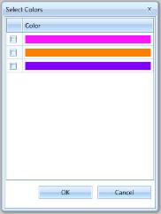
Break
Break
- Select Orange, and click OK.
Break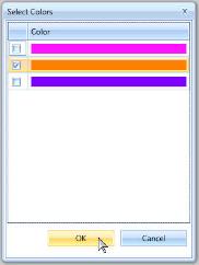
BreakThe Orange points are all selected.
Break - Select Modify to Current Layer.
BreakThe Orange points for our 0.5 Holes are moved.
Break - Repeat this process to put the Red points on the Counterbore layer.
Break
Part 6) Adjusting Layer Order
As a final piece of organization, let's put the two hole layers next to each other. We've seen how we can drag layers, and use the Move Out arrow to get layers out of a group. Now, we use the Move Up arrow to adjust the position of a layer.
- Right-click anywhere in the Layers Manager and select Show All Layers.
Break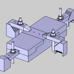
BreakAll entities become visible again.
Break - Highlight the 0.5 Hole layer, and click
 Move Up.
Break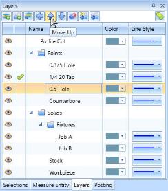
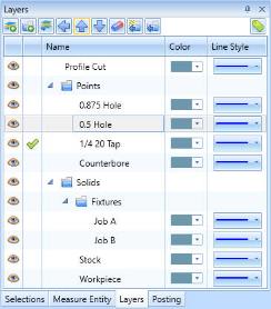
BreakThe position of the layer is updated to put our two hole layers next to one another.
Break
This concludes the example.
If you need further assistance, please contact our support team at (727) 489 – 0003 or [email protected]