Knowledge Base Articles
- BobCAD-CAM V36
- Getting Setup
- Quick Tips & Tricks
- The BobCAD Basics
- Advanced Topics
- Computer Issues
- NC Editor
- Post Processor
- Our Forum
Updating a Post for MDI
Break
Introduction
Beginning with our BobCAM for SolidWorks V10, BobCAD-CAM V35, and BobCAM for Rhino V3 product releases, the MDI feature is now available in Mill and Lathe operations. Previously, this functionality was only available in operations within Mill Turn jobs. To utilize the MDI functionality inside the Mill or Lathe jobs, some simple updates to the post processors are required. This topic will show you how to update the post, and demonstrate generic output.
Default Tasks
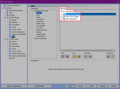
With our MDI functionality, the software defaults to having 3 tasks in the Task List of the MDI page available for usage for standard items:
- Before Tool Change
- After Tool Change
- After Operation
Using our default 3 task names, we will explain how to update the post.
Steps
Break
Step 1) Update the Tool Change / Start Blocks
In this first step, we add the MDI_BeforeToolChange and MDI_AfterToolChange variables in the following blocks:
- Mill
-
2. Start of file standard
-
3. Tool Change
-
4. Null Tool Change
- Not in probe tool changes due to no MDI in probing
Break
-
- Lathe
- 1002. Start of program with turning cycles
- 1003. Tool change for turning
- 1004. Next operation same tool turning
- Navigate to your C:\BobCAD-CAM Data\**Current Version**\Posts\Mill folder and open BC_3x_Mill.BCPst in your preferred text editor.
Break - Scroll to block 2.
Break2. Start of file standard
n,rapid_move_forced, work_plane, force_cancel_offset,"G49",work_coord,cancel_drill_cycle,measure_mode,absolute_coord
" "
"(FIRST CUT - FIRST TOOL)"
system_comment
feature_name_comment
" "
"(TOOL #",list_tool_number," ",tool_diameter," ",tool_label,")"
n,t,"M06"
n,work_coord
output_primary_rotary_index
output_secondary_rotary_index
n,rapid_move,absolute_coord,xr,yr,p_rot,s_rot,s,spindle_on
n,rapid_move,length_offset,d_offset,zr,coolant_onWhere we place the variables for the tasks is where the lines and commands we add to those tasks will appear in the code. This is where we can see some of the flexibility available to us.
Break - In this case we will assume we want the lines we specify in the MDI_BeforeToolChange variable to be called before our tool, and before the tool label we output in parentheses.
Break
Add MDI_BeforeToolChange just above our list_tool_number line.2. Start of file standard
n,rapid_move_forced, work_plane, force_cancel_offset,"G49",work_coord,cancel_drill_cycle,measure_mode,absolute_coord
" "
"(FIRST CUT - FIRST TOOL)"
system_comment
feature_name_comment
" "
MDI_BeforeToolChange
"(TOOL #",list_tool_number," ",tool_diameter," ",tool_label,")"
n,t,"M06"
n,work_coord
output_primary_rotary_index
output_secondary_rotary_index
n,rapid_move,absolute_coord,xr,yr,p_rot,s_rot,s,spindle_on
n,rapid_move,length_offset,d_offset,zr,coolant_on
Break - For our MDI_AfterToolChange variable, we may want to allow our work coordinates and rotary calls to be output prior to any additions we call after the tool change.
Break
Add MDI_AfterToolChange just after the output_secondary_rotary_index line.2. Start of file standard
n,rapid_move_forced, work_plane, force_cancel_offset,"G49",work_coord,cancel_drill_cycle,measure_mode,absolute_coord
" "
"(FIRST CUT - FIRST TOOL)"
system_comment
feature_name_comment
" "
MDI_BeforeToolChange
"(TOOL #",list_tool_number," ",tool_diameter," ",tool_label,")"
n,t,"M06"
n,work_coord
output_primary_rotary_index
output_secondary_rotary_index
MDI_AfterToolChange
n,rapid_move,absolute_coord,xr,yr,p_rot,s_rot,s,spindle_on
n,rapid_move,length_offset,d_offset,zr,coolant_on
Break - Repeat this process for block 3. Tool Change.
Break - We repeat this for block 4. Null tool change as well, but in this case we place MDI_BeforeToolChange after the blank line after feature_name_comment, and before the work_coord line.
Break4. Null tool change
" "
"(NEXT CUT - SAME TOOL)"
system_comment
feature_name_comment
" "
MDI_BeforeToolChange
n,work_coord
output_primary_rotary_index
output_secondary_rotary_index
MDI_AfterToolChange
n,rapid_move,absolute_coord,xr,yr,p_rot,s_rot,s,spindle_on
n,rapid_move,length_offset,d_offset,zr,coolant_on
Break - Press Ctrl+S to save the changes to the post.
Break
Step 2) Update the End of Operation Blocks
Next, we add the MDI_AfterOperation variables to the following blocks:
- Mill
-
197. End of operation – Toolchange
-
198. End of operation - No Toolchange
-
199. End of last operation
Break
-
- Lathe
-
1197. End of operation – Toolchange
-
1198. End of operation – No Toolchange
-
1199. End of last operation
-
- Scroll to block 197.
Break
197. End of operation - Toolchange
n,coolant_off
n,spindle_off
n,optional_stop
Break
- Add the variable MDI_AfterOperation as the last line.
Break
197. End of operation - Toolchange
n,coolant_off
n,spindle_off
n,optional_stop
MDI_AfterOperation
Break
- Scroll to block 198.
Break
198. End of operation - No Toolchange
Break
- Add the variable MDI_AfterOperation.
Break
198. End of operation - No Toolchange
MDI_AfterOperation
Break
- Repeat this for block 199. End of last operation.
Break - Press Ctrl+S to save the changes to the post.
Break
Break
Step 3) Add the 2600-2699 Comment for Future Reference
The 2600-2699 blocks of the posts are the reserved blocks for Custom MDI Commands which allow users and post writers to create custom commands which will be visible within the MDI operation dialog. These blocks can be used two ways:
- Direct output from adding the command.
- Usage of:
- mdi_custom_int_ParamName : allows for output of an integer value.
- mdi_custom_double_ParamName : allows for output of values with decimals.
- mdi_custom_string_ParamName : allows for output of alphanumeric characters.
Part 1) Updating the Post
- Create a line in the graphics area so we have something to apply toolpath to.
Break - Create a Mill 2 Axis feature.
Break
The Mill 2 Axis Wizard appears.
Break
- Select the line as the geometry for the feature.
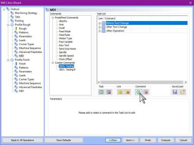
Break - Move to the MDI page and notice the Custom Commands in the Commands list.
Break
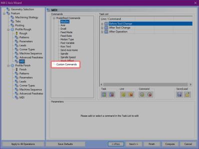
Break
We can see there are currently no Custom Commands.
Break
- Click Finish to exit the Mill 2 Axis Wizard.
Break - Open the post processor and move to the end of the post, and add:
Break
//---------------------------------------------------------------------
// 2600-2699 - Reserved for Custom MDI Blocks
//---------------------------------------------------------------------
This is simply a note for ourselves to remember the blocks available for custom mdi block which should not be used for anything else.
Break
- Skip one line and add 2600..
Break
//---------------------------------------------------------------------
// 2600-2699 - Reserved for Custom MDI Blocks
//---------------------------------------------------------------------
2600. Testing
This adds an item to the Custom Commands.
Break
- Move down a line and add:
Break
//---------------------------------------------------------------------
// 2600-2699 - Reserved for Custom MDI Blocks
//---------------------------------------------------------------------
2600. Testing
" ",mdi_custom_int_Integer
n," ",mdi_custom_double_Decimal
n," ",mdi_custom_string_AlphaNum
This adds each of the variables with names to correspond to their use: Integer, Decimal, and AlphaNum. This also separates them by lines. Notice that while the first does not begin with an "n", the others do. A line number is automatically added for our 2600 block item, but the other lines we created will not have a line number without the "n". We also add the quotes with a space to create a space between the line number and the output of our variables.
Break
- Move down a line and add:
Break
//---------------------------------------------------------------------
// 2600-2699 - Reserved for Custom MDI Blocks
//---------------------------------------------------------------------
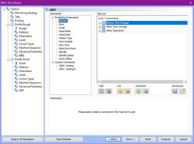
2600. Testing
" ",mdi_custom_int_Integer
n," " ,mdi_custom_double_Decimal
n," ",mdi_custom_string_AlphaNum
2601. Testing B
"D",mdi_custom_int_Int-D,"E",mdi_custom_double_Dec-E,"F"mdi_custom_string_AN-G
This adds each of the variables with names to correspond to their use: Int-D, Dec-E, and AN-G. In this case they are placed on the same line with a prefix in quotes placed before each.
Part 2) Testing the Resulting UI
- In the CAM Tree, under the selected machine, double-click BC_3x_Mill.BCPst to open the Set Post Processor dialog.
Break
The Set Post Processor dialog appears.
- Click OK.
Break
Doing this reassociates the post processor in order to use the updates we just implemented.
Break
- In the CAM Tree, double-click our Feature 2 Axis.
Break
The Mill 2 Axis Wizard appears.
Break
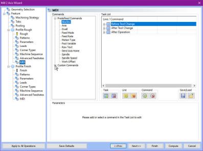
- Move to the MDI page and notice Custom Commands can now be expanded.
Break
Expand Custom Commands.
Break
Part 3) Inserting Commands
Break
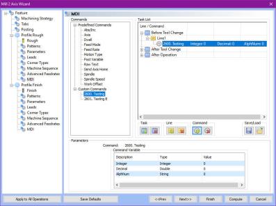
- With Before Tool Change highlighted in the Task List, click our 2600. Testing command, and click
 Add Command.
Break
Break
The Before Tool Change task expands.
Break
- In the Parameters group, update the values to:
Break
- Integer : 1
- Decimal : 2.3
- AlphNum : Four
Break
- Highlight the 2601. Testing B command, click After Operation, then click Add Command.
Break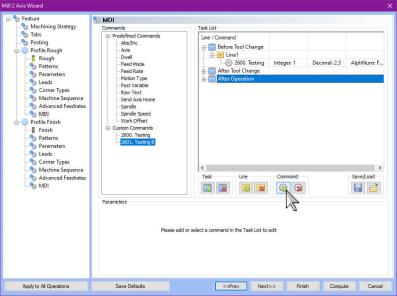
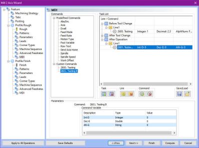
BreakThe After Operation task expands.
Break - In the Parameters group, update the values to:
- Int-D : 5
- Dec-E : 6.7
- AN-G : 8(eight)
Break
- Click Finish to exit the wizard.
Part 4) Posting the Code
- In the CAM Tree, right-click Milling Job and select Post.
BreakThe code is posted.
N02 1
N03 2.3
N04 Four
(TOOL #1 0.5 1/2 FLAT ROUGH ENDMILL - STANDARD)
N05 T1 M06
N06 G54
N07 G90 X0. Y0.265 S595 M03
N08 G43 H1 D1 Z3. M08
N09 Z2.2
N10 Z2.1
N11 G01 Z1.5 F3.3369
N12 X1. F6.6738
N13 G00 Z2.2
N14 Z3.
N15 M09
N16 M05
N17 M01
N18 D5 E6.7 F8(eight)
N19 G90
This concludes the example
If you need further assistance, please contact our support team at (727) 489 – 0003 or [email protected]