Knowledge Base Articles
- BobCAD-CAM V36
- Getting Setup
- Quick Tips & Tricks
- The BobCAD Basics
- Advanced Topics
- Computer Issues
- NC Editor
- Post Processor
- Our Forum
The New Silhouette Feature
The new Silhouette feature allows you to get the overall outline of the part as if it were flattened onto a two-dimensional plane. Getting the outline of a part can be difficult to outright impossible, especially in the case of an STL file. In the past, getting an intersection of curves with an intersecting plane, as seen in the image below, can fail to provide enough to create a proper outline.
Step-by-Step
Using the extract edges or intersection curves feature on a complex part such as the one below can be a time consuming process. The primary reason for this is that these options take multiple steps or leave the user with to little or too much geometry which will need to be cleaned up before being used in the CAM side.
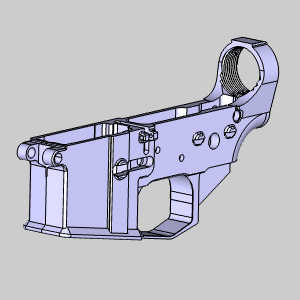
The new silhouette feature however can easily create boundaries of the most common locations that a CAM user would focus on (pockets & the outside boundary) and can easily output the geometry based on the X Y or Z axis or any other custom Axis.


This feature can not be any easier to perform, as the user just selects the geometry and picks the axis that they want the silhouette to be based on before choosing OK. It even works on STL models which prior to this feature would require the user to sketch the boundary manually!
If you need further assistance, please contact our support team at (727) 489 – 0003 or [email protected]