Knowledge Base Articles
- BobCAD-CAM V36
- Getting Setup
- Quick Tips & Tricks
- The BobCAD Basics
- Advanced Topics
- Computer Issues
- NC Editor
- Post Processor
- Our Forum
Open Pocket Example
Break
Introduction
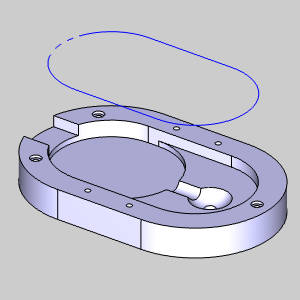
In this example we look at open pocket shapes. We will cover how to create open pockets with wireframe geometry, solid geometry, and what to be cautious of when working with open pockets.
Break
Open Pockets
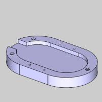
Open pockets are generally the same as pockets. The main difference is an open pocket has an area without a walled boundary at which point we would want our tool to go past the edge, rather than stop before the edge.
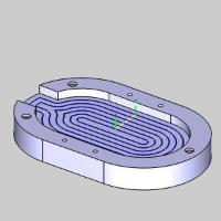
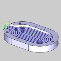
| Open Pocket Geometry | Regular Pocket Toolpath | Open Pocket Toolpath |
 |
 |
 |
Cutting this geometry with the regular pocket toolpath will leave burrs along the open edge, and left over stock from the tool radius between the walls and open edge.
Break
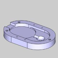
Example
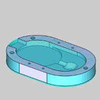
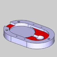
| Final Result | Starting Stock | First Depth | Result After Fist Feature |
 |
 |
 |
|
Break
Part 1) Preparing Geometry
Break
- In the Utilities group, of the Create 2D ribbon, click
 Extract Edges.
Break
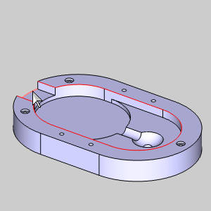
The Extract Edges dialog appears.
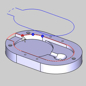
Break - Begin selecting the top inside edge of the part going around to include the two top edges of the slot, and its outer-most edge.
Break
 Brea
Brea
Breakk
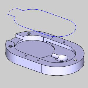
- Select the check box for Project to Z Plane, and choose a height above the part so our part does not interfere with the selection of the wireframe geometry we create.
Break
Break - Click OK.
Break

Break
The geometry is created and projected to height.
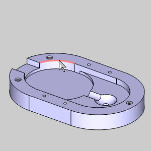
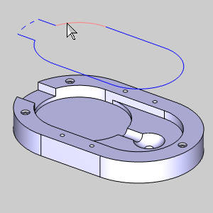
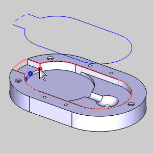
Break - Enter selection mode and select the outer arc of our slot.
Break

Break - Right-click in the graphics area and choose Modify Attributes > Line Style.
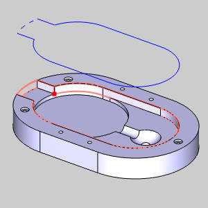
Break - Select any of the dashed/dotted lines to represent the open area of the pocket, and click OK.
Break
Break
The line style is updated.
Break
Part 2) Creating the Feature
- In the CAM Tree, right-click Machine Setup, and select Mill 2 Axis.
Break
The Mill 2 Axis Wizard appears.
Break - Click Select Geometry.
Break
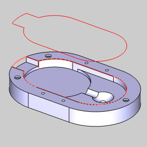
The Feature Geometry Picking dialog appears.
Break - Highlight one of the entities of our extracted geometry, hold shift and click to chain select the entire chain.
Break
Break
The Geometry is added to the Selected Geometry list and the feature preview appears.
Break
At this point we could set the start of our chain, but this is ignored for this example.
Break - In the Feature Parameters section, click in the Pick Top list box of the Top of Feature group.
Break - Although our top of feature is where we intend it to be in this case, hover over the top edge of the part and select one of the snap points.
Break
Break
The point is added to the list, ensuring the proper top of feature, and focus is shifted to the Total Depth group, allowing us to select the bottom of our feature.
Break - Click the top edge of one of our target features.
Break
Break
The proper depth is updated and the feature preview reflects this.
Break - Click OK.
Break
The Mill 2 Axis Wizard returns.
Break
Part 3) Updating Feature Operations and Tool
Break
- In the tree on the left of the wizard, click Machining Strategy to go to that page.
Break - Click
 (Delete Operation) twice to delete both operations from the Current Operations list.
Break - In the Available Operationslist, select Pocket,and click
 (Add Operation) to add the single operation to the Current Operations list.
Break
The Machining Strategy is defined.
Break - Click
 Rough to go to the tool page.
Break - In this case we update the tool to a 0.375 Diameter.
Break - Click Compute.
Break
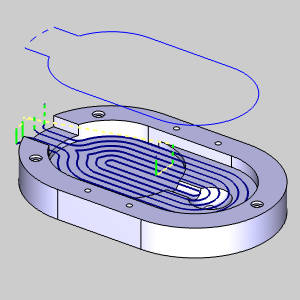
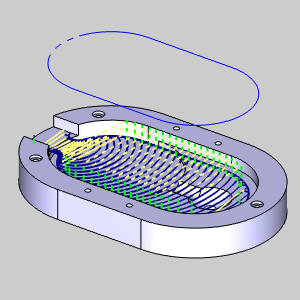
The wizard closes, and the toolpath is computed and displayed.
Break
Break
Currently, this is not the result we are looking for.
Break
Part 4) Choosing the Advanced Pocket Pattern
With the Standard Pocket pattern we first used, open pockets are not possible and we are left with the burred edge and tool radius in the corners we saw in the image of the simulated result. Now, we update the pattern to utilize the Advanced Pocket.
- Edit the feature by double-clicking it.
Break
The Mill 2 Axis Wizard opens.
Break - Click Patterns to move to the Patterns page.
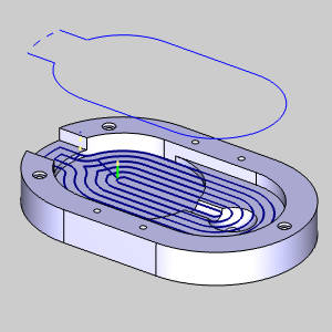
Break - In the Patterns group, select Advanced Pocket.
Break - Click Compute.
Break
Break
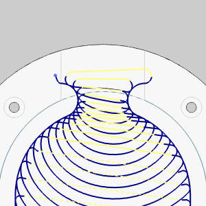
Notice with the same geometry selected, the operation now handles the dotted line differently than the other entities. This is the power of using the Advanced Pocket to create your open pockets.
Break - Edit the feature once more, change the Pattern to Adaptive Roughing, and click Compute.
Break
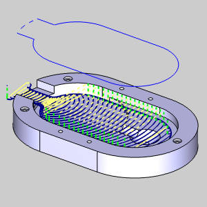
Break
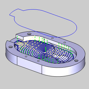
Although each of the Advanced Pocket patterns will handle the dotted line the same, the Adaptive Roughing provides the high speed milling result which is so effective for material removal.
Break
Part 5) Areas of Caution
Let's assume for a moment you have an open area next to walls. Notice the stock we are beginning with in the images below.
| Isometric View | Top View |
 |
 |
With most of the stock already gone, it may seem as though we should update our geometry to something similar to the image below to limit where our open edge is.
- Update the feature geometry and compute.
Break
Break
At first glance, this may seem perfect. However:
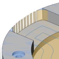
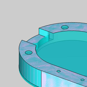
Break - Set the graphics area to a top view, and set the solid to a transparent view.
Break
Break
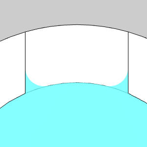
This is where you'll want to use caution when programming open edges.
Break
Notice the way the toolpath rolls out of the open edge and into our walls. This is always the behavior or open pocket toolpath and should be kept in mind.
Break
For this situation, we may want to use the original open pocket geometry. Or, if we are trying to minimize unnecessary moves as much as possible, add offset arc just beyond the tool diameter and handle it as a closed pocket as seen below.
Break
This concludes the example.
If you need further assistance, please contact our support team at (727) 489 – 0003 or [email protected]