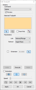
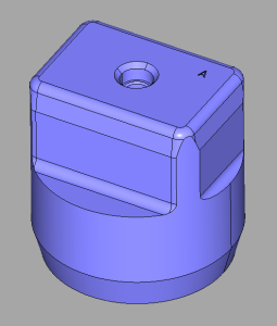
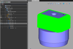
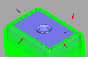
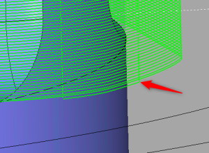
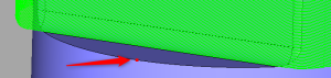
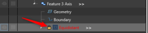
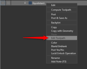
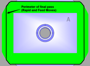
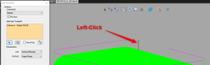
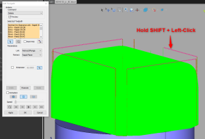
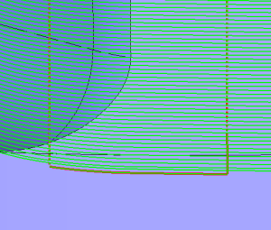
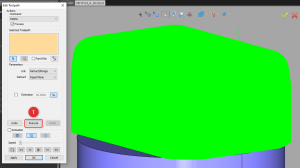
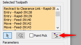
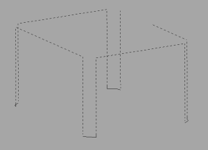
Did you know that you can manually edit toolpath? In BobCAD-CAM, you can refine your toolpath directly with the “Edit Toolpath” utility. When using 3-axis toolpaths like Equidistant or Advanced Z Level Finish, do you sometimes find that there are extra tiny bits of toolpath that are unneeded or unwanted? This function could be exactly what you need to easily remove them. You can use the “Delete” command inside of “Edit Toolpath” to remove these pieces of toolpath. To locate this utility, right-click on an Operation (Not Feature) in the CAM Tree, and select, “Edit Toolpath”. Besides “Delete”, we also have the “Trim and Relink”, “Move”, “Replace”, “Break”, “Modify Attributes” and “Extend Cut Move” commands. These commands allow you to manipulate the toolpath after it has already been computed. In this article, we cover a real-world example of where this tool can be applied to clean up the toolpath and get rid of unnecessary movement. Fig 1 – Edit Toolpath Dialog Box The Edit Toolpath window is shown above. Here, you can see that there is a “Command” section, a “Selected Toolpath” and “Parameters” section that allows you to adjust the parameters of the toolpath and the “Animation” section that allows you to backplot toolpath before you apply the changes. Using this utility can be very powerful. However, in most cases, you should not need to use this as you can utilize the parameters inside the actual features to adjust your toolpath. It is recommended that you only use this utility in cases where there is one or two small areas that you would like to refine toolpath. So, what would be an example of when this may be useful? Fig 2 – Example Part Let’s consider a part like the example above. We will create toolpath for the flat walls on the top half of the part. This can be achieved by using a 3-axis toolpath like “Advanced Z Level Finish” or “Equidistant”. Fig 3 – Equidistant Toolpath At first glance, this toolpath looks pretty good. It has created toolpath in the exact areas we wanted. Fig 4 – Rapid Retract moves However, upon looking closer, we can observe that there are some rapid retract moves that retract all the way from the bottom of the toolpath to the top. Fig 5 – “Extra” Unwanted move And, if you look even closer, you can see that these retract moves are coming from tiny feed moves at the bottom of the toolpath. What we expected to see was one clean and continuous final pass. You may ask, why is this happening? There are a couple of things at play that are causing these seemingly “extra” moves. Fig 6 & 7 – Bottom of Job To make sure the toolpath stays only on the flat wall areas, we set a Bottom of Job a couple thou above the flat floor. (Z-2.498) If we look closer at these tiny entities, in a “Backplot”, we can observe that they are indeed above the Bottom of Job set for this Equidistant Operation. The lowest Z value in the “extra” entities is -2.49825. Given that our Bottom of Job is set to -2.498 and our Machine tolerance set to 0.0005, this toolpath is within the parameters set for the feature. Even though these moves are within the parameters, these toolpaths are still unneeded and unwanted. So, why did they get created in the first place? This has to do with the way that the toolpath gets computed in the background. When you hit the compute button, toolpath first gets created as if there are no boundaries or Top and Bottom of Jobs set. Then, it will trim the toolpath according to those constraints set by the user. So, how can we clean up this toolpath? There are many different things you can do to clean up this toolpath. There are usually always at least a few different ways you can approach your job creation. 1. Different Toolpath Operation: You could try to use a different operation altogether (like Advanced Z Level Finish). Toolpath operations generate differently and may give you a better result. 2. Adjust Toolpath Parameters: You could try adjusting the Bottom of Job higher to trim more toolpath. 3. Use Edit Toolpath utility: In our case, there are only a few entities that we want to remove and we are happy with the rest of the generated toolpath. So, using “Edit Toolpath” is a quick and effective way to eliminate this unwanted toolpath. Important Note: When using this utility, make sure this is your last step in your programming process. This is because once you have edited your toolpath, the Operation will be “locked”. This means that you will be unable to make any changes to the toolpath parameters. Fig 9 – Locked Operation After “Edit Toolpath” You can unlock the Operation and recompute toolpath. However, this will get rid of your toolpath edits and you will need to redo the edits you made. So, we are just about ready to post out the g-code and send it to our machine. It is now time to edit our toolpath to eliminate these extra moves before posting the code. 1. Right-Click on your Operation (Not the Feature) and select “Edit Toolpath” If we observe these feed and rapid moves that contain the tiny moves, we can notice that they are all connected together. This is because they are all part of the final pass in the toolpath and have been partially trimmed like we observed in the “Backplot” previously. Because of this, we can use the Chain Select method that is used for CAD when selecting lines, arcs, or splines. To Chain Select, Left-Click on the entity where you want to start the chain. Then, Hold SHIFT + Left-Click on the last entity of where you want to end the chain. (Follow steps 2 and 3) 2. Left-click on starting Rapid move In this case, this happens to be the last move in the toolpath. 3. Hold SHIFT + Left-Click on the Rapid move (Up to the point at which you want to delete.) Observe that it will highlight all the moves in between the Start and End of the Chains selected. We can zoom in and observe that our tiny moves are indeed selected. 4. Press “Execute” Observe that all Rapid and Feed moves are deleted at once. 5. Hit “Apply”. Then, “OK” to apply all changes. 6. Right-Click on “Milling Job” and Select “Simulation” to observe the final toolpath and make sure there will be no issues with the newly revised toolpath. Alternatively, you can use the “Animation” section inside of the “Edit Toolpath” dialog to see the tool movement. This completes the overview of the “Edit Toolpath” utility inside of BobCAD-CAM. This is just one example of how you can be effective at utilizing this tool. However, you can apply this same workflow when using other commands like “Move” to move toolpath or “Modify Attributes” to change the properties of a toolpath (eg. Convert a Rapid Move to a Feed Move). Bonus Tip: Did you know that you can convert your Toolpath into selectable CAD geometry (Lines and Arcs)? Inside the “Edit Toolpath” dialog, click the icon at the bottom right of the toolpath selections (See image below). This will create geometry on the currently active layer in your Layers – Manager.
If you need further assistance, please contact our support team at (727) 489 – 0003 or [email protected]Knowledge Base Articles
How to Manually Edit Toolpath
![]()
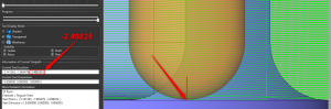
Fig 8 – Z value (Inside Backplot of Equidistant Toolpath)Clean up Toolpath:
Before we get started:
Manually Edit Toolpath Step-by-Step
BobCAD-CAM V36
Getting Setup
Quick Tips & Tricks
The BobCAD Basics
Advanced Topics
Computer Issues
NC Editor
Post Processor
Our Forum
Created: December 2, 2022