Knowledge Base Articles
- BobCAD-CAM V36
- Getting Setup
- Quick Tips & Tricks
- The BobCAD Basics
- Advanced Topics
- Computer Issues
- NC Editor
- Post Processor
- Our Forum
How To - Find Direction of Rotation & Rotary Mode
This document defines the steps taken to determine the Rotary Axis Mode and the Direction of Rotation. First, we will go over the different rotary output modes, then get into the steps to determine the mode and direction of rotation.
Rotary Axis Position Output Modes
When a machine has a rotary axis or axes mounted it is very important to understand the way the controller is configured to program the positions of the rotary axis. Because of this, the BobCAD-CAM posting engine supports multiple Rotary Axis Position Output Modes. These modes are defined on Post Question: 440.
440. What is the rotary output type (0=Abs Pos 1=Signed ABS 2=Signed Continuous) ? 0
There are 3 different output modes supported. Each mode is defined below:
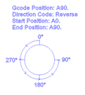
0 – Absolute Position Mode
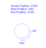
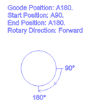
In this mode, the rotary locations are defined as an absolute position and do not change. The direction is defined by a separate G or M code in the NC file. Using this mode tells the posting engine to output the indexing direction string values that are defined on Post Questions: 710. thru 713. Examples of different positioning using this output mode are shown below.
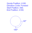
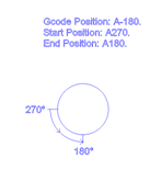
1 – Absolute Position Signed Direction
In this mode, the rotary locations are defined as an absolute position and do not change. The direction is defined by positive or negative rotary position values in the NC file. Using this mode tells the posting engine to output the indexing positions using the positive or negative values to define the direction the machine to move the rotary axis. Examples of different positioning using this output mode are shown below.
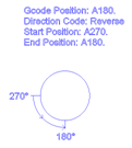
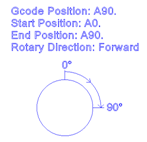
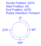
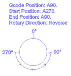
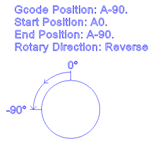
2 – Signed Continuous
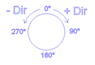
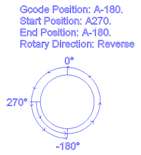
In this mode, the rotary locations are defined in a positive or negative position. The positions are best understood if you think of a number line where you have positive values going to the right and negative positions to the left with Zero in the center. Wrap up that number line into a circle and you have the positions for the rotary axis.
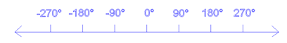
As shown on the number line above the position of A90. and A-90. are NOT the same location. The direction is defined by the location of the new position relative to the current position in the NC file.
Finding Direction of Rotation:
To find the direction of rotation we must first understand the two different types of rotary axis configuration.
Rotary on Tool
Rotary on Part
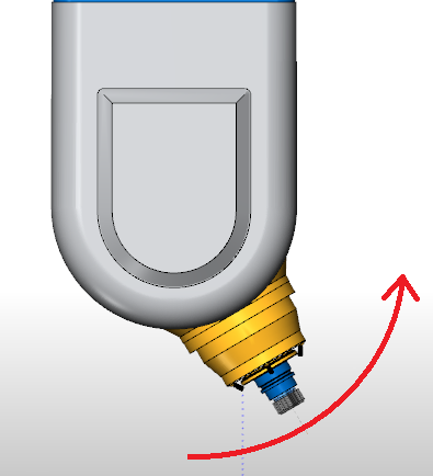
Rotary on Tool - This type of rotary when moved will rotate the angle of the tool itself. This is commonly seen on Head/Head 5 axis machines or on Head/Table 5 axis machines. The direction of rotation for the physical rotary axis is also the same direction the tool is moving in the part as shown in the image below.
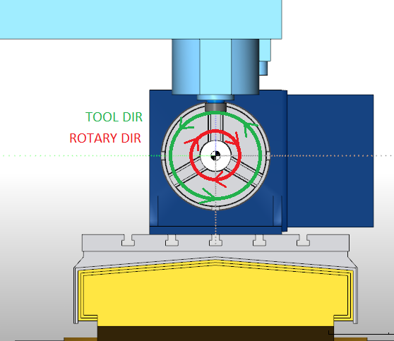
Rotary on Table - This type of rotary is mounted to the table and rotates the workpiece. This is your more common 4 axis rotary, or the 2nd rotary axis found on a Head/Table 5 axis configuration, or either of a Table/Table assembly found on 5 axis machines. When the rotary axis moves, it is rotating the workpiece. The important thing to understand with this type is: The direction of rotation of the physical rotary axis is the opposite direction the tool is moving in the physical part.
The rotary axis is defined as a rotation vector based on the Right-Hand Rule. Using this rule we can identify and align the base coordinate system and rotary axes, and directions. The following image shows the standard coordinate system and how the “Right Hand Rule” aligns.
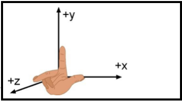
For the rotary axes. The following standard is applied:
- Rotation around the X axis = A
- Rotation around the Y axis = B
- Rotation around the Z axis = C
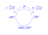
The direction of rotation is determined by looking down the axis vector to the origin for the rotation axis. The following image shows a rotation of CCW direction when looking from the X positive to the origin. When the rotation matches this example the rotation direction in the software will be positive.
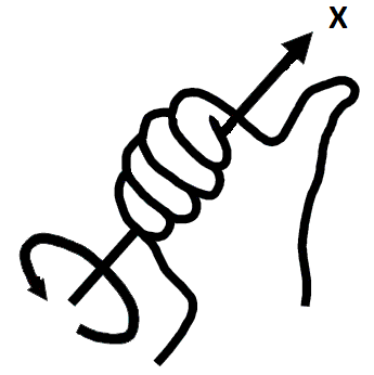
For a Head Head type machine, this direction would have the tool moving CCW in the workpiece.
For a Table based rotary machine, this direction would have the tool moving CW in the workpiece however the rotary unit itself would be moving CCW. When answering the question for rotary axis direction make sure you are answering based on the direction the rotary axis itself is moving.
Testing to determine Rotary Axis Mode
The following steps will walk you through determining what mode the machine controller is using for the rotary axis positions.
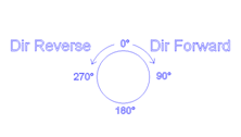
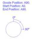
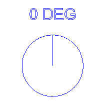
1. Looking at the rotary device. Think of the 12 o.clock position as zero as shown in the following image:
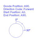
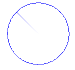
2. Using MDI on the machine, rotate the axis to a position of 45 degrees (Positive). Note the location the rotary moves to:
| Example Positions for this Step Based on Mode | ||
| Absolute Position Mode | Absolute Position Signed Direction | Signed Continuous |
 |
 |
 |
Based on the result of this step you can determine the direction of rotation. Remember to keep in mind that you need to define the direction of rotation based on the direction the physical rotary axis is moving.
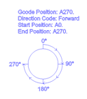
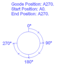
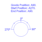
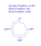
3. Using MDI on the machine, rotate the axis to a position of -45 degrees (Negative). Note which location (Shown Below) the machine moves to:
| Example Positions for this Step Based on Mode | ||
| Absolute Position Mode | Absolute Position Signed Direction | Signed Continuous |

Does not move or rotates 360 Degrees |
 Does not move or rotates 360 Degrees. If rotates 360 Degrees, the direction should be opposite of step 2 Does not move or rotates 360 Degrees. If rotates 360 Degrees, the direction should be opposite of step 2 |
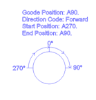
Moves a total of 90 Degrees in the opposite direction of step 2 |
You should now be able to determine if the machine is running in Absolute Position mode or in Signed Continuous mode.
If the machine always rotates in the same direction regardless of position, then the rotary mode is most likely Absolute Position mode which will use G or M codes to define rotation direction. This mode is typically only used on Horizontal milling machines where simultaneous motion is not used (Indexing Only).
If you need further assistance, please contact our support team at (727) 489 – 0003 or [email protected]