Knowledge Base Articles
- BobCAD-CAM V36
- Getting Setup
- Quick Tips & Tricks
- The BobCAD Basics
- Advanced Topics
- Computer Issues
- NC Editor
- Post Processor
- Our Forum
Basic Job Setup, Toolpath Creation and Posting G-Code
This document is made to give new BobCAD users a basic understanding of how to set up a job, create toolpath and post out code for a Mill, Plasma, Laser or Waterjet machine. Follow through the example below:
Mill / Plasma / Laser / Waterjet Step-by-Step
1. Open BobCAD and go to File --> Open to open an existing 2d geometry file (such as a .DXF file) OR make a new file and create 2d geometry using the Create 2D tab.
2. Go to the CAM Tree window, right click on CAM Defaults and select New Job.
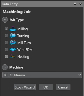
3. The Machining Job page will pop up. Select Milling then choose your Mill/Plasma/Laser/Waterjet machine from the drop-down box below.
4. Click the Stock Wizard button to start the job setup.
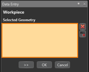
5. The Workpiece tab is used for 3D models and does not apply in this application. Hit the >> (Next Arrow) button to continue to the Stock Definition page.
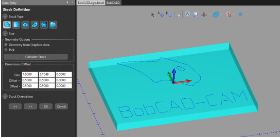
The stock will automatically be created based on the X,Y max and min values with a default value of 1 inch for the Z thickness.
6. Add .5" to the Offset values for X +/- and Y +/- to extend the stock edges out and change the Z Dim to a 0.5" thickness.
7. Hit the >> (Next Arrow) button to continue to the Machine Setup page.
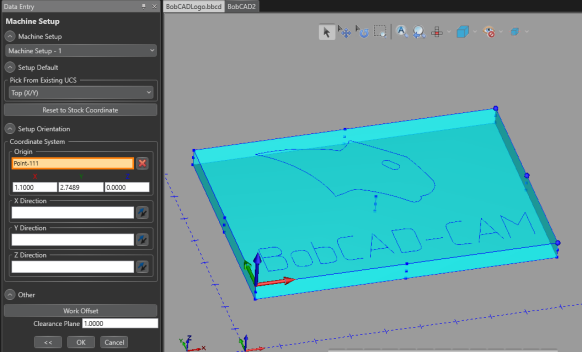
8. The Machine Setup page is where you will set up your machine origin (machine zero).
9. Click inside the Origin box to activate it. (it will highlight orange)
10. Click on the point in the bottom left corner of the stock to move the machine origin to the bottom left position.
11. Hit the OK button to finish the job setup.
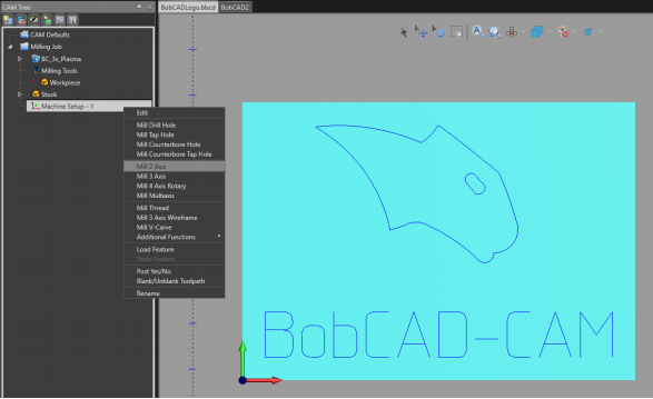
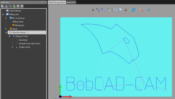
12. Right click on Machine Setup – 1 and select Mill 2 Axis from the drop-down menu

13. Click the Select Geometry button
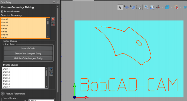
You can ignore the Feature Parameters in this application because you will not have a Z movement on your machine.
14. Drag a box over all the geometry to select it.
15. Hit the OK button
- Important Note: When dragging a box over the geometry, you have to be careful. If there are any double lines overlapping each other, the toolpath will be created for every line highlighted. As a safety measure, you can either try cleaning up the geometry first or you can simply hold SHIFT + Click on each chain you want to select instead to insure that you only select one line for each chain.
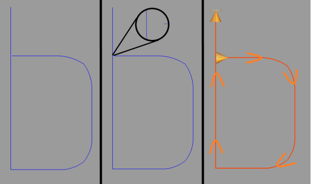
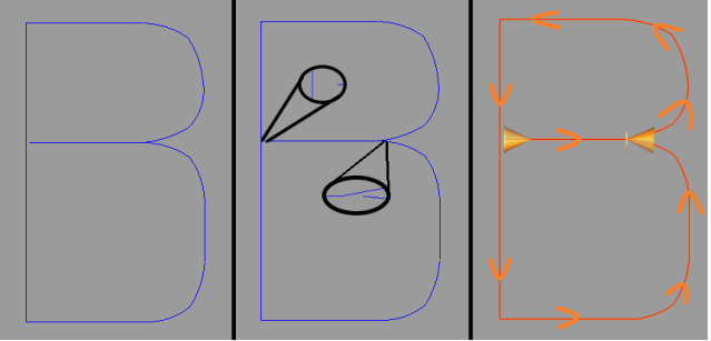
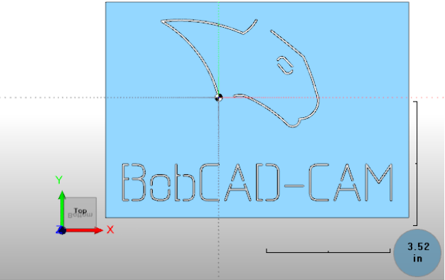
- Important Note: When using letters, you may run into issues with the toolpath not being created for the entire letter. This is because of the letter’s geometry. Those letters are not an open or closed chain. If you have a letter like “b” or “p”, the letters intersect themselves (unlike the letters “C” or “D”). A “C” would be an example of an open chain and a “D” would be an example of a closed chain. To fix the letters like “b” or “p”, you will create a gap in-between the intersection to make it one single opened chain. If you created the letters in BobCAD, go to Utilities --> Explode to break up the letters into lines and arcs. Then, use the Break Screen function in the same Utilities tab to break the desired geometry. Then, delete the arc or line section that is intersecting the letter. If you take a look at Pic. 7.3 and 7.4, you can see how the geometry was created in order to create one single chain for each letter.
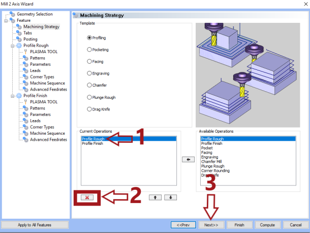
16. Make sure the Profile Rough Operation is highlighted and hit the Delete Operation (Red X) button
17. Click the Next button
The tabs page will create spaces along the chain where the tool will not fire. This will hold the desired pieces in place so that they do not fall out of the stock when the part is being machined.
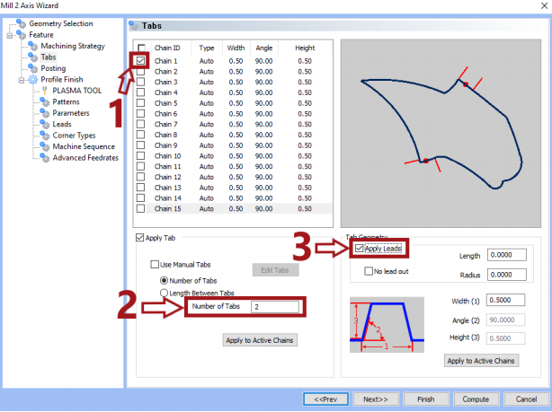
18. To automatically add Tabs to the geometry, click on the box to the left of the chain you want to add tabs on.
19. Type in the Number of Tabs you would like for the chain
20. Check off the box that says Apply Leads and make sure you have the Length and Radius values set to zero. (This step is needed to create a rapid move where the tab is located.)
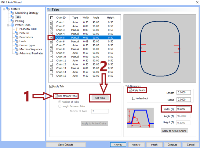
21. To place tabs in a specific location on the chains, check off the box of the desired chain (make sure it is highlighted)
22. Check off the Apply Leads box and set a smaller Width of the tab (0.09) for the letters in this example
23. Check off the Use Manual Tabs box and click the Edit Tabs button
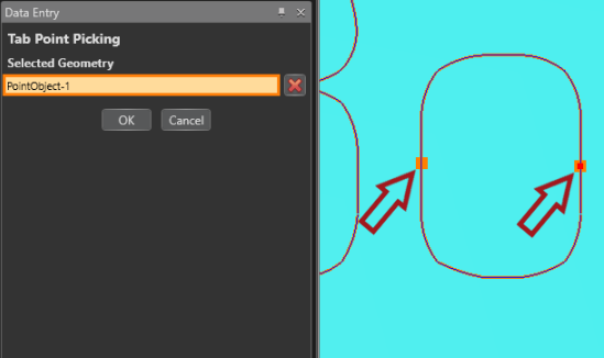
The orange dots on the chain signifies the location of the tabs.
24. If there is already a tab in a spot you do not want, click on the dot to eliminate it. Then, just click on the places where you want to place the tabs
25. Hit the OK button
26. Click the Next button
- Note: Do not try to add all the tabs you want at the same time for all the chains. You create tabs on one chain at a time. Whichever chain is highlighted from the tabs page. If you want tabs on other chains, you will need to select the specific chain you want to apply them on and then follow steps 21-25 again for that desired chain.
27. Click the Next button until you get to the Tool page
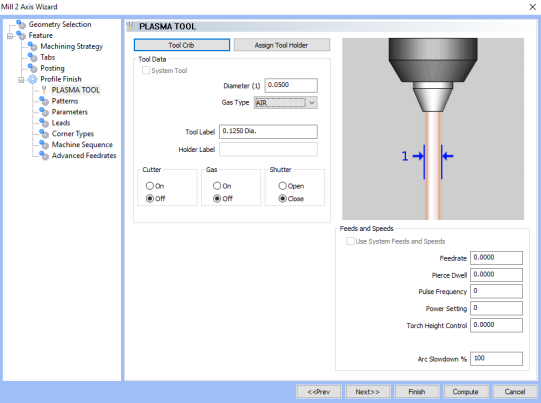
28. Setup your tool parameters and hit the Next button
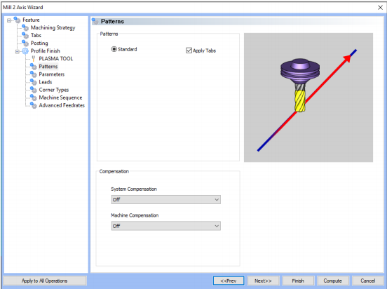
Turning System Compensation off, will create toolpath that runs the tool down the center of the selected geometry.
29. On the Patterns page, in this example, change the System Compensation drop-down menu to off
30. Click the Next button
31. Leave all other settings default and hit the Compute button to create the toolpath
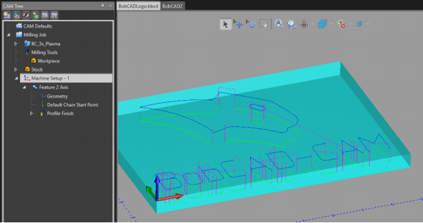
32. Go to the Milling tab at the top and select Start Simulation
33. Click the Run button to run the simulation and observe the toolpath
34. Click the (Cancel Simulation) button to close the simulation.
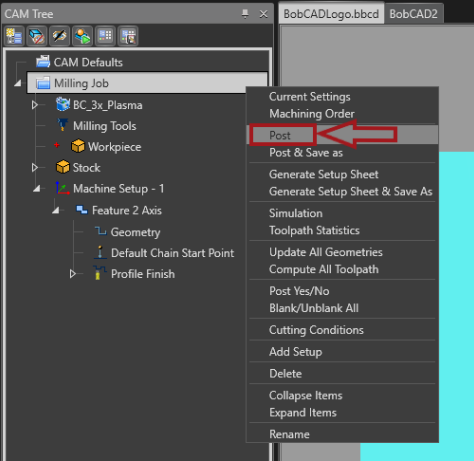
35. In the CAM Tree, right click on Milling Job and select the Post option to post out the G-code.
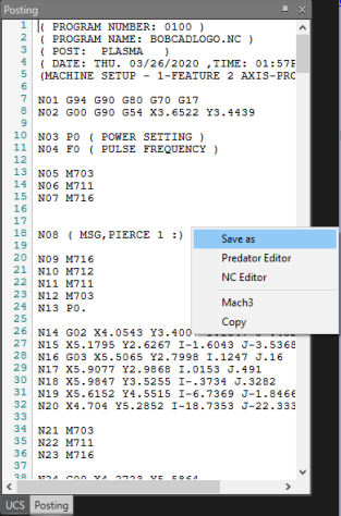
36. The G-code will show up in the Posting Window. Right click inside the window and select the Save as option to save the NC file.
If you need further assistance, please contact our support team at (727) 489 – 0003 or [email protected]