Knowledge Base Articles
- BobCAD-CAM V36
- Getting Setup
- Quick Tips & Tricks
- The BobCAD Basics
- Advanced Topics
- Computer Issues
- NC Editor
- Post Processor
- Our Forum
Finding the Center of Rotation for Tilt Rotary Unit Mounted on Table
In the BobCAD-CAM system when using the multi-axis features your machine must be properly defined. The calculations that must be performed for proper G Code creation depends on an accurate definition of your machine’s kinematics. This document covers how to find the center of rotation for a Tilt Rotary unit so the machine parameters can be correctly defined.
There is a simple test you can use to find the necessary values and we will walk you through this process here in this document.
Locating the 1st required point
The 1st point we need to locate is at the center of the face of the rotary platter. The following image shows the location of the point we are looking for.
NOTE: This document shows a tilt/rotary unit that when at Zero, Zero location has the tilting axis sitting where the rotary is aligned to rotate around the X axis. If your zeroing your assembly at a different location simply apply what you see here to your orientation.
Pic. 1 - Center of Rotation for a Rotary
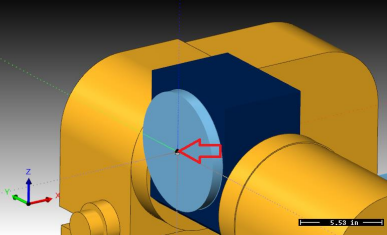
To find this location on your machine, use a tool to touch the face of the platter to find your X axis component. Use the bottom of the tool to touch off the edge of the rotary platter then account for the radius of the platter to get the point at the center.
The values we need are X and Z. Write them down on the last page in the location labeled Point 1
(X1, Z1).
Locating the 2nd required point
To find the 2nd point you need to rotate the tilting axis to a position that will hold the rotary platter so it is parallel to the Z axis of the machine tool. The following image shows the location we are looking for.
Pic. 2 - Center of Rotation for a Rotary
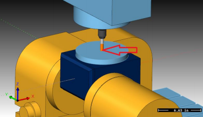
To find this location on your machine use a tool to touch off the edge of the platter or use an indicator to tram in the XY center of the platter. Use the bottom of the tool to find the face of the rotary platter.
The values we need are X and Z. Write them down on the last page in the location labeled Point 2 (X2, Z2).
Use BobCAD-CAM to plot intersection point
In this step we will use BobCAD-CAM to find the location of the rotation center for your tilt rotary unit. To do this we will plot the two points on the screen and construct geometry to locate the center of rotation.
We are going to locate the 1st point in the BobCAD system at 0,0 on the screen and the 2nd point will be relative to the 1st point. To do this we need to subtract the two point values so we end up with the difference from the 1st point to the 2nd. Here is the math to do this:
X1 – X2 = ____________ Z1 – Z2 = ____________
Now in the BobCAD system you need to create the 1st point. Create a point at X0.0 Y0.0 Z0.0 on the screen.
Next create the 2nd point using the resulting values from the math found on the previous page.
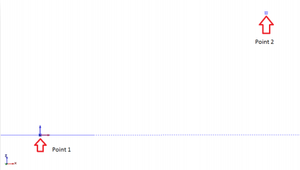
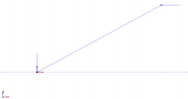
These two points represent the same location on your tilt rotary unit when the unit is in the two different positions. The image below shows an example of what you should have on your screen looking from a FRONT view.
Pic. 3 - Point 1 and Point 2
We need to create some reference geometry for the two different orientations. The objective here is to create geometry on the 2nd point that represents the same relative location as it is on the 1st point. The following steps will walk you through this process
Point 1 in the TOP UCS – Create a line from the 1st point location up in Z that is 1.000 long. Endpoint Data:
X0. Y0. Z0. (1st Point Location)
to X0. Y0. Z1.
Point 2 In the TOP UCS – Create a line from the 2nd point location over in X that is 1.000 long.
Use the Create\Line\Angle option to create this line. Set the Angle to 0
and click the 2nd point as the start point.
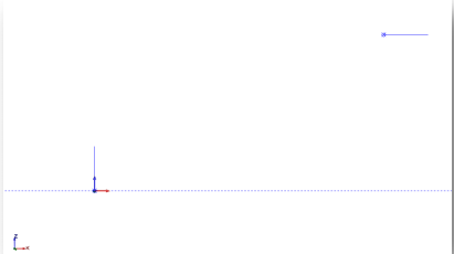
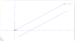
The result of creating this geometry should be two lines. Each line starts on one of the points and the other endpoint represents same point for the tilt rotary in the 2nd position. The following image shows the result of this step.
Pic. 4 - One inch Lines Attached to Point 1 & 2
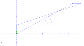
Now we connect the two ends of our reference geometry to each other by connecting the relating endpoints to each other. Use the Create\Line\Continuous command to do this. Next create a perpendicular line in the center of each of the two lines joining the reference geometry.
Create reference line from point 1 to point 2
Pic. 5 - Connecting Points 1 & 2
Pic. 6 - Offsetting the Line Made in Pic 5
Now we create construction geometry used to construct a perpendicular line. Set the USC to FRONT. Next offset the join line by 1.000 down using the Create\Line\Parallel command. The following image shows the result of this step.
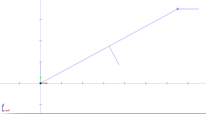
Next create a line from the mid-point of the 1st join line to the construction line just created. The following image shows the result of this step.
Pic. 7 - Connecting the Mid Points
Now delete the construction line as you no long need it. The following image shows the result of this step.
Pic. 8 - Deleting the Offset Line
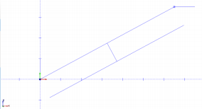
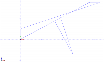
Now repeat the same steps to create the join line and perpendicular center line for the 2nd endpoints of our reference geometry. The following image shows the result of these steps
Pic. 9 - Connecting the one Inch Lines Made in Pic 4
Use the Trim Two option to trim the two perpendicular lines to each other. The intersection point of these two lines is the center of rotation. The following image shows the result of these steps.
Pic. 10 - Using the Extend Function
Using the dimension command, you can locate the location of the center of rotation relative to the 1st point location. The following image shows the result of these steps.
Pic. 11 - Center of Rotation
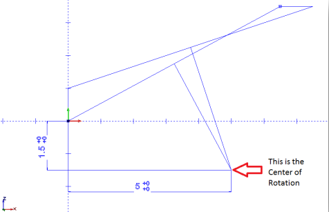
This X and Z dimension are the values you will use to define the Center Point location in the Machine Parameters for the tilting axis when building your machine definition.
Data Values - Keep this document for your records!
Point 1 Point 2:
X1 = _______________ X2 = _______________
Z1 = _______________ Z2 = _______________
Difference result values from Point 1 to Point 2
X1 – X2 = ____________
Z1 – Z2 = ____________
Center Point Values (relative to 1st point)
X = _______________
Z = _______________
If you need further assistance, please contact our support team at (727) 489 – 0003 or [email protected]