Knowledge Base Articles
- BobCAD-CAM V36
- Getting Setup
- Quick Tips & Tricks
- The BobCAD Basics
- Advanced Topics
- Computer Issues
- NC Editor
- Post Processor
- Our Forum
Feeds and Speeds in BobCAD-CAM
Speeds and Feeds in BobCAD-CAM can be set up in a couple of different ways. This article will discuss the different ways you can set up your feeds and speeds and give you a good understanding of where and how these options are utilized.
Feeds and Speeds
Feeds and Speeds refer to the feed rates and surface speeds used for tool motion that get output in the g-code NC file. This is typically denoted by Fn for the Feeds and Sn for the Speeds. (n = value) The typical unit of measure for feeds is in Units per Minute (Inch per Minute or MM per Minute) and the typical unit for speeds is in Surface Feet per Minute (SFM).
In BobCAD-CAM, these feed and speed values can be found on the Tool Page of each operation, inside the feature wizard. (See Fig. 1 below)
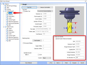
Fig. 1 – Feeds and Speeds options on the Tool Page for a Profile Rough Operation
To navigate to this tool page, right-click on the current operation you want to view in your CAM Tree and select “Edit”. By default, there will be values already displayed in the Feeds and Speeds portion of this tool page.
The default Feeds and Speeds that you see here in are based on the Tool selected for that operation (Number of Flutes, Tool Material) as well as the Stock Material selected for that Job.
Material Library
In BobCAD-CAM, there is a Stock Material that gets set up for every job. Expand your “Stock” in the CAM Tree to view your material for the job.
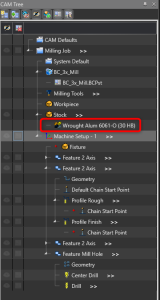
Fig. 2 – Current Material for a Milling Job
Depending on the Material selected for the job, you will get different feed and speed values displayed on the tool pages. You can set up your own default values by modifying these materials in the “Material Library”.
To edit these Materials, you can either right-click on the Material in the CAM Tree and select “Edit” or you can navigate to the “CAM” tab and click the “Material Library” icon.
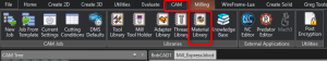
Fig. 3 – Material Library icon in the CAM tab
There will be a default library that already has many different materials such as; Steel, Aluminum, Alloys, Plastic and Titanium. However, if you do not see a material already listed, you can create new materials by clicking the “Add Group” button.
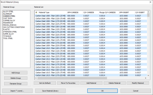
Fig. 4 – Material Library Dialog box
Note: It is recommended to keep a backup copy of your Material Library once you have finished editing the library. Close out the software when done and navigate to the BobCAD-CAM Data folder here: C:\BobCAD-CAM Data\BobCAD-CAM V35\Technology . Select the Material Library file is called, “MaterialDB.xml”. You can copy and save this file (Or any library in this folder) to a backup location (ex. Cloud storage) to ensure that you will not lose these files in case your computer crashes for instance.
You can make modifications to the already existing material. This will adjust your default Feeds and Speeds that get output. You can do this by selecting the material. In this example, we have selected, Carbon Steel 1045 – Plain (125-175 HB). Then, click “Modify Material”.
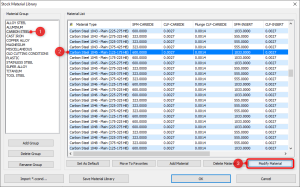
Fig. 5 – Modify Material for Carbon Steel 1045 – Plain (125-175 HB)
This will bring up the Stock Material Feeds and Speeds dialog box. This is where you can modify existing feeds and speeds or add new tool materials to handle different tools.
You have the “Tool Materials” section on the left-hand side that shows all tool materials currently setup, a “General Feeds and Speeds” section to define the overall feeds and speeds that will be used (Setup SFM, SFM-Tapping, Chip Load Per Flute and Plunge Chip Load) and a “Customized” section that allows you to more finely adjust these default values based on Tool Type and Operation.
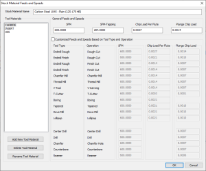
Fig 6 – Stock Material Feeds and Speeds Dialog Box
The Default Feeds and Speeds that display on the Tool Page are based on two things. 1. The Tool (Number of Flutes and Tool Material) and 2. The Stock Material setup for the job. (Note: if using “Customized” it would also account for the tool type and operation)
Once you have finished making your modifications, you can see the results back on the Tool Page of your Feature Wizard. The example in figure 7 shows the updated tool and Stock Material for the job (Tool: 1/2 Endmill number of flutes 4, Tool Material CARBIDE and Stock Material Carbon Steel 1045 – Plain (125-175 HB))
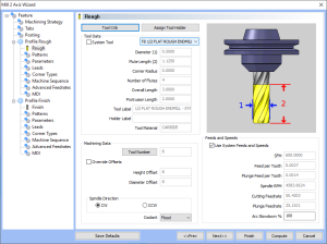
Fig. 7 – Stock Material Carbon Steel 1045 – Plain (125-175 HB), Tool Num Flutes 4, CARBIDE Tool Material
As stated at the beginning of this article, Feeds are typically denoted by Fn and Speeds are typically denoted by Sn (n = value). For a standard Fanuc-based post processor, Spindle RPM in BobCAD-CAM would be denoted by Sn in the g-code, and the Cutting and Plunge Feedrate would be denoted by Fn. Looking at the example below, you can see the result of posting out this Milling Job.
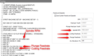
Fig. 8 – (BC_3x_Mill.BCPst) Fanuc-based G-Code showing Feedrates and Spindle RPM
Manual Setup of Feeds and Speeds
Sometimes, you may want to manually adjust these values to tweak them, or you want simply to manually enter them in as you create your toolpath. If this is the case, simply uncheck the “Use System Feeds and Speeds” checkbox on the Tool Page inside the feature wizard. Then, manually enter the values. In the example below, 5000 was entered for Spindle RPM. You will notice that other fields auto-adjust based on what was changed. (ex. Cutting Feedrate went from 50.42 to 55)
The software uses Feed and Speed equations to automatically calculate other fields.
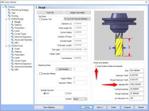
Fig. 9 – Uncheck “Use System Feeds and Speeds” and Adjust Spindle RPM to 5000
In this case, a Spindle RPM of 5000 was entered. The equation to find the feedrates are as follows:
Eq. 1
![]()
So,
![]()
And,
![]()
However, if you do not want to use these equations to automatically calculate these feedrate values, note that you can adjust them after adjusting the Spindle RPM to whatever value you wish. The Spindle RPM will stay at 5000. As shown below, the Cuttting Feedrate was set to 60 and the Plunge Feedrate was set to 30. However, the Spindle Speed stayed at 5000.
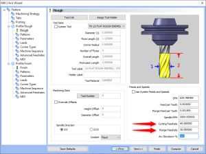
Fig. 10 – Update Cutting and Plunge Feedrate
This is how you can manually adjust your Feeds and Speeds inside of the BoBCAD-CAM. This should give you a good overview of the different options inside of BobCAD-CAM and help you understand where you can set up Feeds and Speeds inside the software.
If you are wanting to find out what feeds and speeds should be used in your jobs, there are many other great online resources at your disposal. You can find some basic calculators on Theoretical Machinist (http://theoreticalmachinist.com/RPM_Feed_Calc.aspx).
However, if you are looking for a more robust Speeds and Feeds calculator that goes much more in-depth, the G-Wizard Speeds and Feeds Calculator by CNC Cookbook is a great option (https://www.cnccookbook.com/g-wizard-feeds-speeds-calculator-mill/). You can set up your Machine, Stock Type, Tool, and Cutting parameters among other options to get more accurate feeds and speeds calculations.
If you need further assistance, please contact our support team at (727) 489 – 0003 or [email protected]