Knowledge Base Articles
- BobCAD-CAM V36
- Getting Setup
- Quick Tips & Tricks
- The BobCAD Basics
- Advanced Topics
- Computer Issues
- NC Editor
- Post Processor
- Our Forum
Facing Off a Spoil Board
When facing a spoil board in BobCAD, the user will first need to setup the stock, machine setup, and toolpath before sending the code to the machine. This document will provide a brief tutorial on how you might go about creating and Posting a CAM Job using a Facing Operation for the spoil board.
Step-by-Step
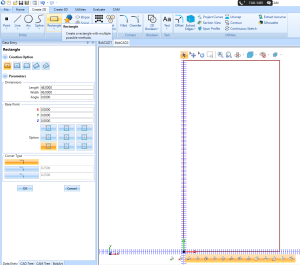
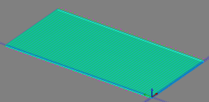
1. In the Create 2D tab, select the Rectangle option.
2. For the length and width of the rectangle, input the values of the spoil board that is being faced.
NOTE: This example will use a 4’ x 8’ spoil board or 48” x 96” (Length x Width).
3. In the Base Point section, select the bottom left corner option to place the geometry in the upper right-hand quadrant. Click OK, then Cancel.
Pic. 1 Drawing the Spoil Board
4. Right-click on CAM Defaults in the CAM Tree and select New Job.
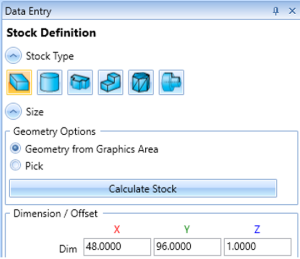
5. For the “Job Type”, select Milling and choose your machine from the drop-down if it's not already there by default. Then, click Stock Wizard.
6. On the Workpiece page, no workpiece needs to be selected. Click the ">>" forward arrow button
7. In the Stock Wizard, make sure the X dimension is set to 48 and the Y dimension is set to 96. Then, click ">>".
Note: If you made the geometry before starting a New Job, the stock should automatically generate to the correct size in this case.
Pic. 2 Stock Wizard Page
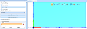
8. On the Machine Setup page, leave the machine origin set to X0, Y0, Z0 . Then, click OK.
Pic. 3 Setting the Machine Setup Origin Page
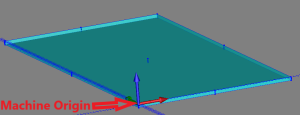
Pic. 4 Machine Origin Location
9. Right-click on the Machine Setup – 1 in the CAM Tree and select Mill Facing.
10. On the Geometry Selection page, no action is needed. The software will use the info from the Stock Wizard that we setup in the previous steps. Click, Next.
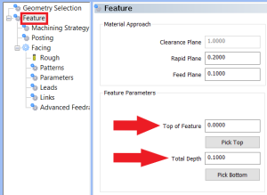
11. On the Feature page (shown in the image below), keep the Top of Feature set to the default as this value is automatically set to 0.0000. This is because our top of the stock is in relation to the Machine Origin. Adjust the Depth to the depth of cut from the top of the spoil board. In this example, we will leave this value set to 0.1000. Click, Next until you get to the Tool Page (Rough).
Pic. 5 Setting the Total Depth of the Facing Operation
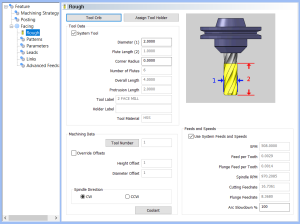
12. On the Tool Page (Rough) (shown in the image below), choose the tool that will be used in the facing feature. In this example, a 2 Diam Face Endmill will be used.
Note: To access this tool from the Tool Library, click on Tool Crib > Add From Tool Library. Sort by Diameter by clicking on Diameter column at the top and find the default tool called, "2 Face MILL". Select it and click OK. Then, OK again. Click, Next.
Pic. 6 Setting the Correct Facing Tool
13. On the Patterns page, set the Stepover (Distance between each pass) for the feature. The default is set to 50%. For this example, set the Stepover to 75%. This would set the Stepover distance to 1.5 inches. We will leave the other pages left to the default settings and click Compute at the bottom right.
Pic. 7 Computed Mill Facing Toolpath
14. If all looks good and you are happy with the toolpath, right-click on Milling Job in the CAM Tree and select Post to see the G-Code for the job. You can verify the g-code by looking through the posting window or right-click inside the Posting Window to select NC Editor to verify and make edits to the g-code inside of NC Editor.
15. If you are happy with the results and want to send the G-Code to your machine, Right-click in the Posting window and click Save As to save to a flash-drive. If you are in the NC Editor, go to File > Save > Save As to save to a flash-drive or go to the Tools tab and click Start DNC Transfer to send the g-code through a RS232 cable.
If you need further assistance, please contact our support team at (727) 489 – 0003 or [email protected]