Knowledge Base Articles
- BobCAD-CAM V36
- Getting Setup
- Quick Tips & Tricks
- The BobCAD Basics
- Advanced Topics
- Computer Issues
- NC Editor
- Post Processor
- Our Forum
Defining Machine Setup in Lathe
The Machine Setup for Lathe is defined using SolidWork's native Coordinate Systems. The article below will provide instructions on how to setup these coordinate systems in SolidWorks.
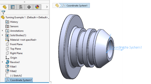
Creating a Coordinate System in SolidWorks
1. Go to the Features page in SolidWorks
2. Hit the Reference Geometry drop down box
3. Under Reference Geometry, create a Coordinate System
4. Left Click on the Selections Box and select where the Coordinate System shall be centered around
5. For the X Axis, Y Axis, and Z Axis select a line that is parallel to the Axis.
6. Click on the green check mark
NOTE: Make sure the Coordinate system you define in SolidWorks has the Z axis along the center of rotation. In Machine setup select this coordinate system for the Machine Setup.
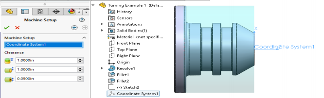
After the coordinate system is defined you can define your clearances on the same page. The 3 parameters are described above.
If you need further assistance, please contact our support team at (727) 489 – 0003 or [email protected]