Knowledge Base Articles
- BobCAD-CAM V36
- Getting Setup
- Quick Tips & Tricks
- The BobCAD Basics
- Advanced Topics
- Computer Issues
- NC Editor
- Post Processor
- Our Forum
How to Create Surfaces to Fill In Gaps on Model
This document will walk you-through how to create surfaces and how to stitch surfaces together to create one solid model. This will allow you to use the model with other Create 3D functions to modify the model further. It will show how to construct and deconstruct a cube with fillets to help you get an idea of how the process of creating solids and surfaces work inside of BobCAD.
Step-by-Step
Pic. 1 - Example for this Article: A Cube with Missing Surfaces
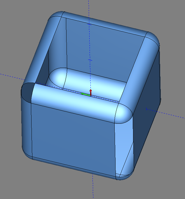
Pic. 1 shows a Cube model that will be used in this example. It has three missing surfaces.
Creating the Cube with Missing Surfaces - Part 1
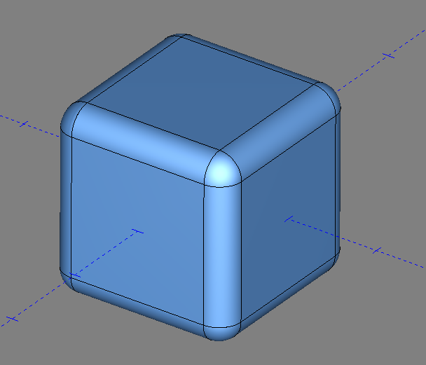
Pic. 2 - Cube
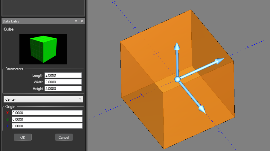
1. Go to Create 3D and select Cube
2. Set the Length, Width and Height to 2, if not already by default
3. Press OK then Cancel
Pic. 3 – Fillet Cube
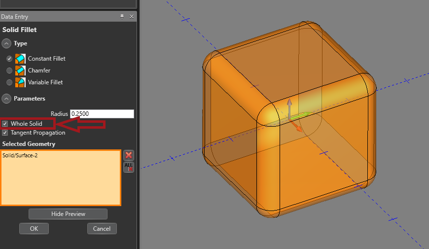
4. In the Create 3D tab, select Solid Fillet
5. Check off the box that’s says, “Whole Solid” and select the Cube as the Selected Geometry
6. Press OK then Cancel
Pic. 4 – Stitch Solid Menu
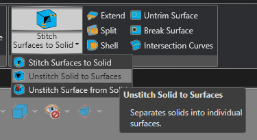
7. In the Create 3D tab, click the drop-down menu where it says, “Stitch Surfaces to Solid”
8. From the menu, select Unstitch Solid to Surfaces
Pic. 5 - Unstitch Cube
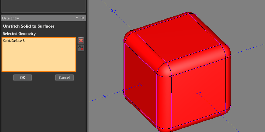
9. Select the Cube as the Selected Geometry
10. Press OK then Cancel
Pic. 6 – Delete Surfaces
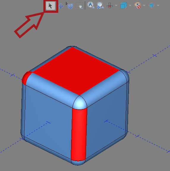
11. Enter Select Mode by selecting the ![]() (Select Mode) icon at the upper left of the graphics area
(Select Mode) icon at the upper left of the graphics area
12. Select the three surfaces that you want to delete
13. Press the Delete button on your keyboard
Creating Surfaces and Stitching Model - Part 2
The second half of this document will describe how to recreate the missing surfaces. You can then stitch the surfaces together to create a solid model. Creating a solid model will allow you to use other 3D functions in the software to modify the model such as the Boolean Add/Subtract, Extrude Boss/Cut and Solid Chamfer/Fillet functions.
Pic. 7 – 3 Missing Surfaces
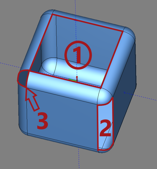
Pic. 7 shows the model we created in the previous steps above. It shows the three missing surfaces.
Pic. 8 – Layers Window
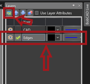
The Checkmark signifies which layer is active. Geometry created will be placed in the active layer.
1. Go to the Layers Window and select the ![]() (New Layer) icon
(New Layer) icon
2. Name the newly created layer “Edges” and make sure the Checkmark is selected for the Edges Layer.
Pic. 9 – Extract Edges
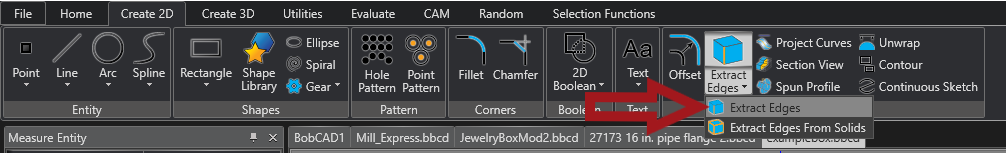
3. Go to the Create 2D tab and Select the Extract Edges function
Pic. 10 – Extract Edges Selection
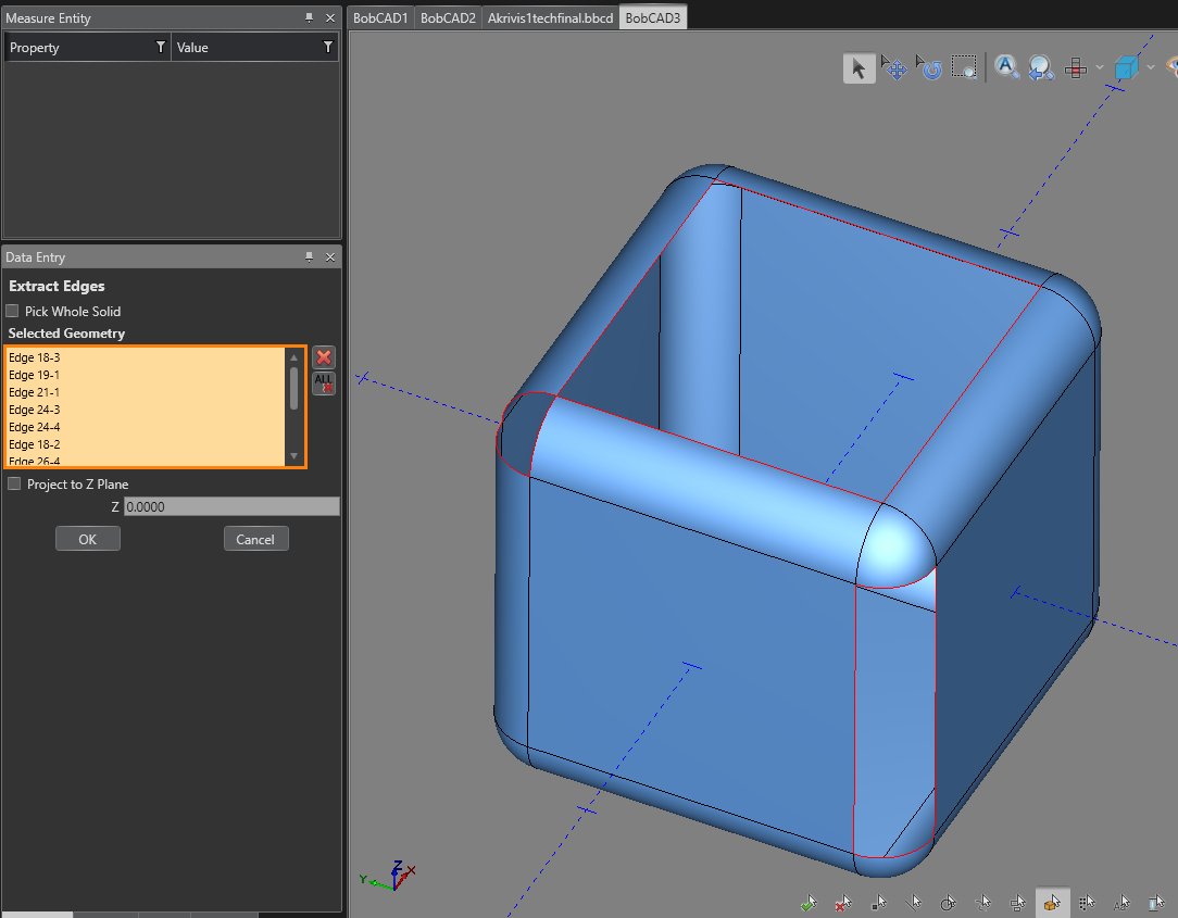
Note: Make sure the Project to Z Plane box is unchecked
4. Select the Edges of the three missing surfaces from the existing surfaces
5. Press OK then Cancel
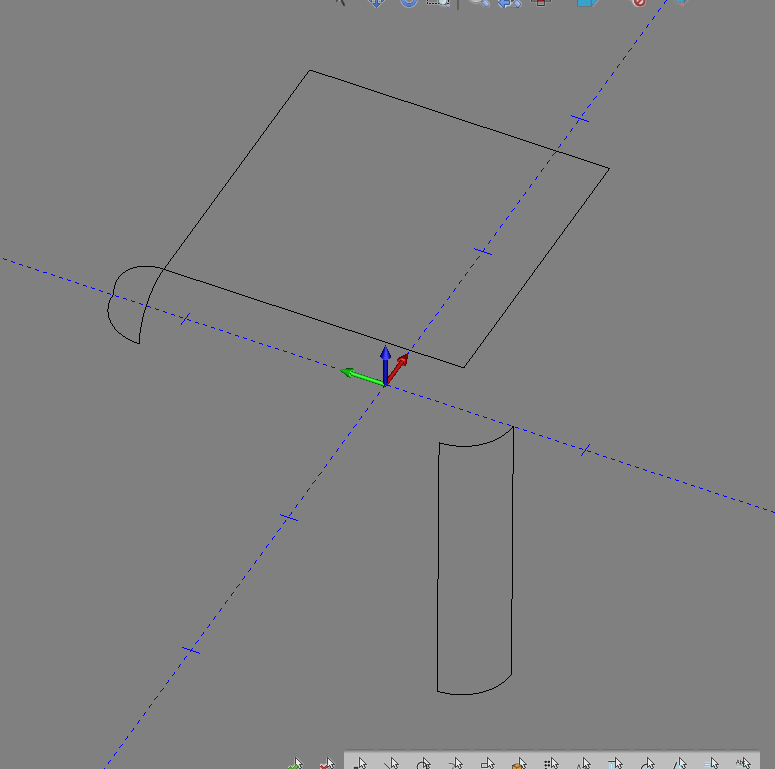
Pic. 11 – The Extracted Edges
6. Go back to the Layers Windows and blank out the existing surfaces by clicking the ![]() (Hide) icon on the layer named “CAD“.
(Hide) icon on the layer named “CAD“.
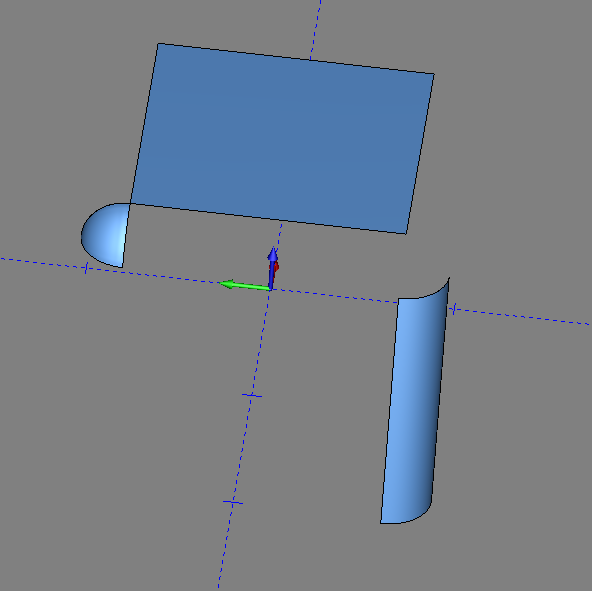
Pic. 12 – First Surface Creation (Planar Surface)
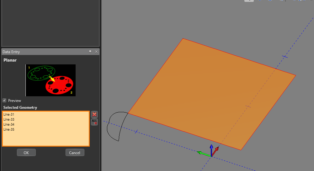
7. Go to the Create 3D tab and select the Planar surface function in the Surfaces group
8. Select the top four lines for the Selected Geometry to create a flat surface at the top of the model
9. Press OK then Cancel
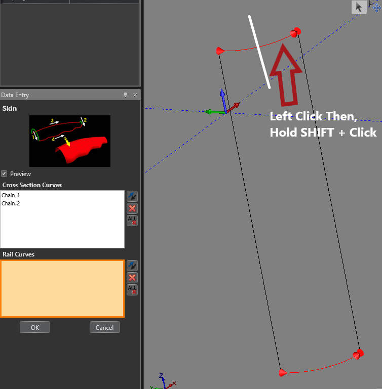
Pic. 13 – Second Surface Creation (Skin Surface)
10. In the Create 3D tab, select the Skin function in the Advanced Surfaces group
11. The Cross Section Curves box will already be active (highlighted orange). Create two chains opposite from one another (shown in Pic. 13).
Create a chain by clicking on one half of the entity to start the chain. Then, Hold SHIFT + click in the same location to complete the chain. Make sure that the chain face the right direction shown on the example in the Data Entry Window.
- Click inside the Rail Curves box to make it active. (It should highlight orange)
- Create two more chains with the other two lines perpendicular to the Cross Section Curves.
Pic. 14 – Skin Surface Preview
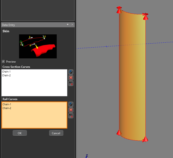
Note: Once all chains are created, there will be a preview show up of the surface
12. Press OK then Cancel
Pic. 15 – Third Surface Creation (3 Edges Surface)
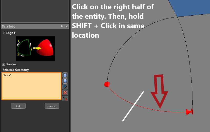
13. In the Create 3D tab, Select the 3 Edges function in the Surfaces group
14. Create three chains, all moving in the same direction, for the Selected Geometry (one for each arc)
Pic. 16 – 3 Edge Surface Preview
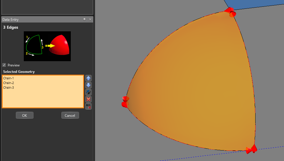
15. Press OK then Cancel
Pic. 17 – Planar, Skin and 3 Edge Surfaces Created
Pic. 17 shows the three surfaces created
Pic. 18 – All surfaces for the Model
16. Go to the Layers Window and unblank the rest of the surface by selecting the furthest box to the left of the “CAD” layer (The ![]() (hide) icon will appear)
(hide) icon will appear)
Pic. 19 – Stitch Surfaces to a Solid Model
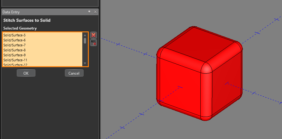
17. In the Create 3D tab, select the Stitch Surfaces to Solid function
18. Drag a box over all the geometry to add it to Selected Geometry
19. Press OK then Cancel
Pic. 20 – Completed Solid Model
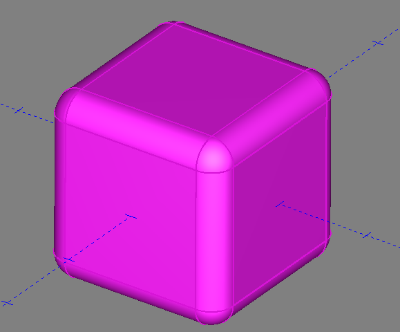
Pic. 20 shows the completed solid model after stitching all the surfaces together. You can now use other Create 3D functions to modify the model such as Boolean Add/Subtract, Extrude Boss/Cut and Solid Chamfer/Fillet.
Pic. 21 – Boolean Add Two Solids
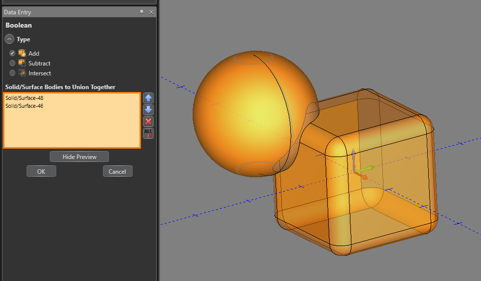
20. In the Create 3D tab, create another solid that intersects the cube
21. Also, in the Create 3D tab, select the Boolean function
22. Make sure the Add box is checked off and select both solid models
23. Press OK then Cancel to combined both models into one solid
If you need further assistance, please contact our support team at (727) 489 – 0003 or [email protected]