Knowledge Base Articles
- BobCAD-CAM V36
- Getting Setup
- Quick Tips & Tricks
- The BobCAD Basics
- Advanced Topics
- Computer Issues
- NC Editor
- Post Processor
- Our Forum
Clearance Plane Application in 5 Axis
What is Clearance Plane and how is it applied in BobCAD?
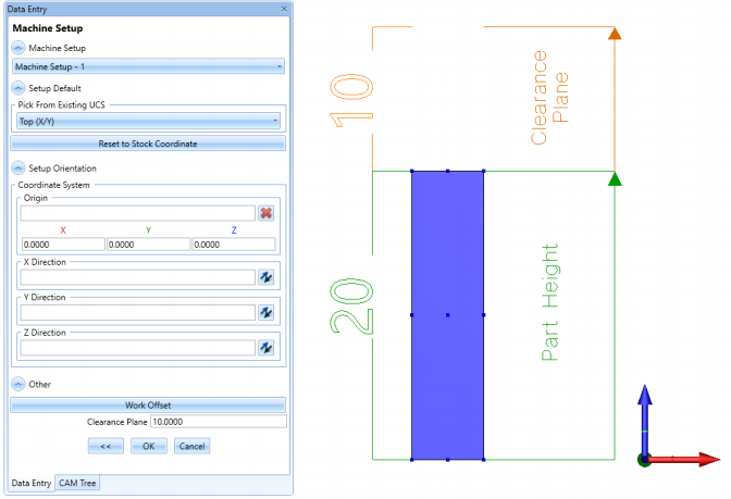
Clearance plane defines the safe rapid plane used between machining operations for tool changes to get in position for the next operation. This can be set in the Machine Setup page of BobCAD. The clearance plane is usually applied from the top of stock plus the clearance value you’ve numerically defined in the Z direction in 2 and 3 axis.
In 5 axis (head to head), depending on where your you’re indexing, the clearance plane is applied with respect to your tool orientation and machine zero. For this example, we’ll be taking a look at a 20x10x5in. block with a 0.5in chamfer defined in the corner with a clearance plane of 10inches.
Pic. 1 - Front View of Part & Clearance Plane
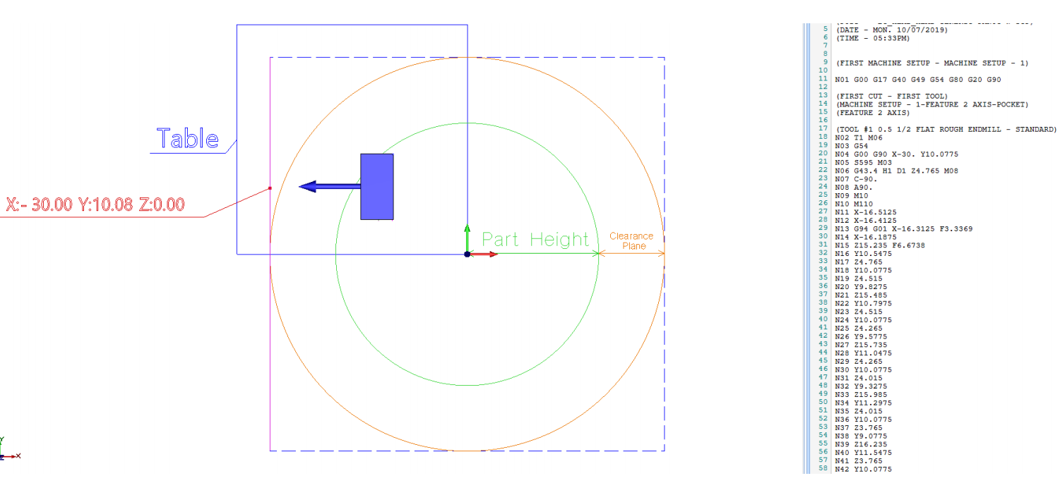
Pic. 2 - Clearance Plane for 5 Axis When Indexing From +X Axis
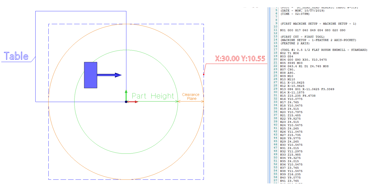
In the photo above, the blue square represents the table, the green circle represents the spherical part height, the orange circle presents the clearance plane, and the blue dotted square is the limit of the clearance in X and Y. The machine zero is placed at the lower right hand corner of the table and is indexed to be machined normal to the surface indicated by the blue arrow.
As the tool is engaging to that surface, you’ll notice that the point plotted is outside the blue square (table limit). In other words, the tool is starting outside the table limit before it hits the surface so clearance is applied by adding the height of the part plus clearance value set at the machine zero. The red dot presents line N04, where X30 would be the height of the block (20in) plus the clearance value (10in). If the tool is starting is coming from the positive x direction there will be an overtravel outside of the table (blue square).
Pic. 3 - Clearance Plane for 5 Axis When Indexing From -Y Axis
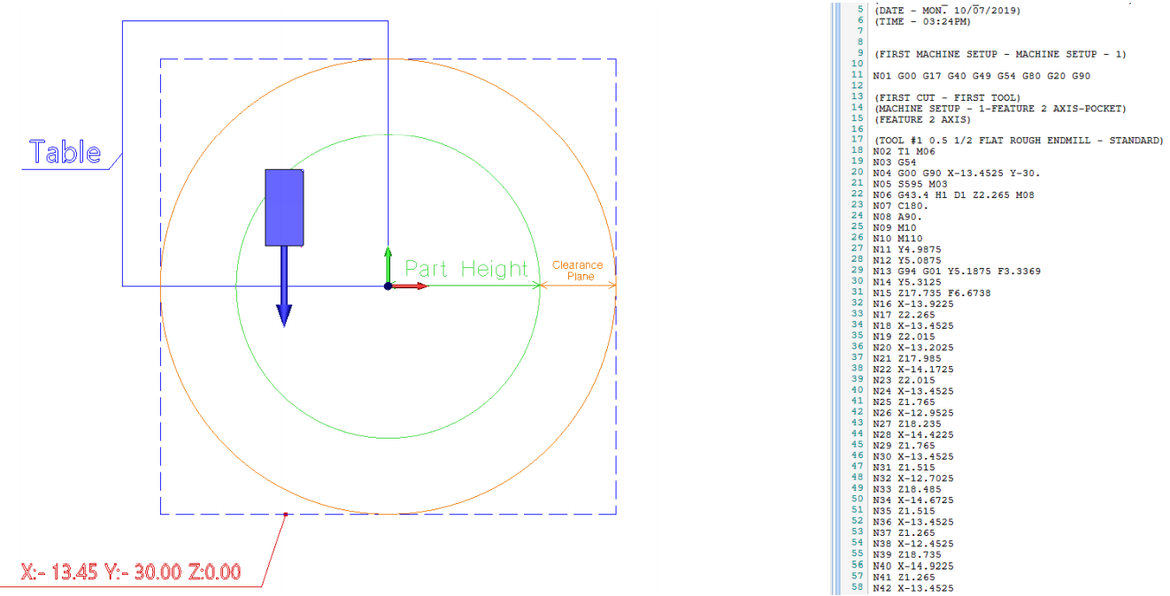
Here is another example of an overtravel. There is an index at the bottom surface in the -Y direction and when the point is plotted out, you’ll notice that the location of that point is outside of the table limit. Therefore, clearance will be applied at the machine zero from the part height plus the clearance value which will result in an overtravel.
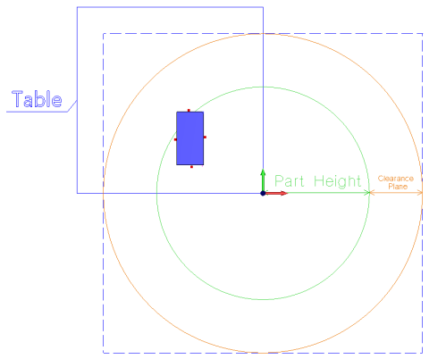
Pic. 4 - Clearance Plane for 5 Axis When Indexing From +Y Axis
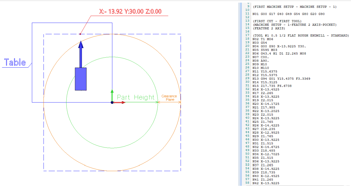
In this example, there is an index applied at the top surface in the positive Y direction. From the point plotted, you’ll notice in line N04 that the point lies within the blue square which is within the limit of the table. Clearance is applied exactly from the part height plus the clearance value.
Pic. 5 - Clearance Plane for 5 Axis When Indexing From -X Axis
From the picture above, the applied clearance point is within the table limit when it’s indexed from the negative x direction.
The Solution:
To solve this issue altogether, compress the clearance plane small enough so that the software will consequently use the rapid plane for clearance. The minimum clearance plane value that will work would be have to be twice the part height in the negative (for example, if part height is 20in, clearance plane should be at least -40in).
When you compress the clearance plane, you’re telling the software that there is technically no clearance plane and the next plane that it will go off of is the rapid plane.
Pic. 6 - Side View of Clearance Plane for 5 Axis
By making the clearance plane small enough, you can see from the image that all points (red dots) are now at the 0.2in rapid plane for the clearance. By doing this, you can completely control what the clearance is for each operation because you can set the rapid plane to whatever value you want in the feature wizard of that operation. This will eliminate the overtravel issue no matter where your machine zero is positioned or how big your part is.
If you need further assistance, please contact our support team at (727) 489 – 0003 or [email protected]