Knowledge Base Articles
- BobCAD-CAM V36
- Getting Setup
- Quick Tips & Tricks
- The BobCAD Basics
- Advanced Topics
- Computer Issues
- NC Editor
- Post Processor
- Our Forum
Building a 5 Axis Rotary Tilt in BobCAD
Using machine simulation for 4 and 5 axis part programming offers huge benefits to developing collision-free toolpath. In order to take advantage of this feature, you’ll need to build a machine within your BobCAD CNC software.
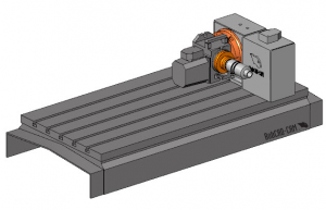
When building a machine, you’re defining your machine’s “kinematics”, which is really just a fancy word for how the machine moves and its configuration. You’ll also want to add geometry, like the machine base & rotary products to use in collision checking groups.
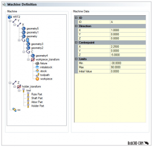
Where is the Machine’s Zero
Now, this may seem like an obvious step, but for me, it was a huge mistake that cost me a lot of time and frustration. Before you start anything, you have to understand where the machine zero will be for your exact build. This is important because the “offsets” you’ll use; the machine components all need to be based on this one location.
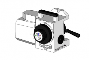
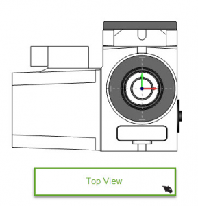
In our example below, the zero will be on the face of the HA5C collet.
This mistake cost me a lot of time and frustration. When I first built this setup, I had the zero at the centerline of the A axis. This caused all kinds of issues in latter steps, so don’t fall for the same thing. Understand where the machine zero will be for your configuration before you do anything else!
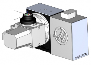
Machine Component Models
Most machine OEM will provide you with models & if they don’t, they will have a print with dimensions so you can create your own. In our example, we are using the supplied models from HAAS; they are good like that!
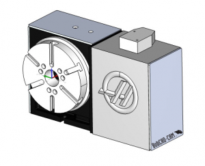
What we need to do at this point is to align the 2 models so that match our setup. When I opened the X_T models from HAAS, both of the rotary product’s zero was at the face and on centerline.
Starting with the HA5C, we need to rotate the model so it’s facing straight up as it would be attached to our HRT210, making sure to keep the face of the collet at zero.
Next, we need to align the HRT210 to the HA5C as they would be on the machine. There is an adapter plate that HAAS offers which I did not have any information on at the time of this build. So, I moved the HRT210 into position so that both the HA5C and the HRT210’s rotary axis intersected.
NOTE: To work with both rotary products in the same file, I used file merge. This way the HRT210 and the HA5C file are in one CAD file. I also made sure each rotary product was on its own layer. Doing so made it easy to select/view each rotary product independently. After the file merges, I saved the file as a BBCD, as not to alter the original X_T files.
With this example, I needed to move the HRT210 down 5 inches in Z and over 2.25 In X. This translation aligns both rotary products. It also provides us with the offset distance from the face of the HA5C to the HRT210 axis of rotation. We’ll use this information in future steps.
Saving STL Files
Now that we have both rotary products relative to each other with a known offset value, we are ready to save out our STL files. When building a machine, we use STL files for the machine components. We will “add geometry” when editing the machine’s definition.
When saving the machine components, the start of the file name must match the name of the machine you are building.
When saving the rotary products, you’ll have to save 2 files for reach rotary product. One for the part of the rotary product that rotates, the other being based on the rotary product that doesn’t rotate.
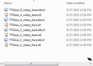
Note: Be sure to save each component out as an STL and BBCD file. This way, if you need to make any changes, you have the sold models to work off of.
For more information about the naming of the models, click here.
If you need further assistance, please contact our support team at (727) 489 – 0003 or [email protected]