Knowledge Base Articles
- BobCAD-CAM V36
- Getting Setup
- Quick Tips & Tricks
- The BobCAD Basics
- Advanced Topics
- Computer Issues
- NC Editor
- Post Processor
- Our Forum
How to Apply Cutter Compensation in BobCAD-CAM (G41/G42)
This article will cover cutter compensation in BobCAD and how to get a G41/G42 to appear in the processed G-Code. It will also talk about how to apply a Wear Compensation as well.
Pic. 1 - Compensation on the "Patterns" page
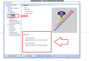
As you can see in Pic. 1, the Compensation options can be found in the "Patterns" page in the "Mill 2 axis" feature wizard. By default, System Compensation is set to "Left" and Machine Compensation is set to "Off". Machine Compensation controls whether G41/G42 is turned on or off.
This Machine Compensation can be found when using the "Mill 2 Axis" feature with a "Profile Rough", "Profile Finish", "Chamfer Mill", "Corner Rounding" and "Drag Knife" Operation.
Pic. 2 - Machine Compensation (G41/G42)
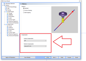
If you look at Pic. 2, Machine Compensation is activated using the drop-down menu. There are two possible combinations to consider.
1/ Standard Cutter Compensation
System Compensation = "Off" | Machine Compensation = "Comp left / G41" or "Comp right / G42"
In this scenario, there is no compensation applied in BobCAD and you are leaving it up to the controller to compensate the full tool diameter when reading the G41/G42.
You can observe in the software that the toolpath itself, after computing the toolpath, does not get offset relative to the geometry selected and runs down the center of the geometry. This is because System Compensation is turned off. The X, Y values will be posted relative to the original geometry while also outputting a G41/G42 in the g-code to compensate at the machine.
2/ Wear Compensation
System Compensation = "Left" or "Right" | Machine Compensation = "Comp left / G41" or "Comp right / G42"
In this scenario, both compensation types are turned on. This allows the user to apply a Wear Compensation on the controller to only account for wear on the tool for the G41/G42 values instead of the full tool diameter.
You can observe in the software that the toolpath in BobCAD does in fact get compensated based on the tool diameter set for that feature. This means that in the posted code, the X, Y values will already reflect the tool being compensated AND it will also post out a G41/G42 to allow you to apply the Wear Compensation at the controller.
Pic. 3 - Apply a Lead-in
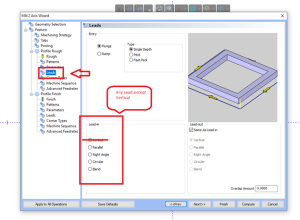
An important note about Cutter Compensation in BobCAD-CAM is that you need to make sure that you apply a NON-VERTICAL LEAD-IN AND LEAD-OUT on the "Leads" page of the feature to have the g-code post out a G41/G42/G40. The reason for this is because the G41/G42/G40 gets applied on the first Lead-in line of the operation and the last lead-out line move.
Note: When using "Circular" or "Blend", make sure the "Length" is NOT set to zero.
Pic. 4 - Check the posted Code
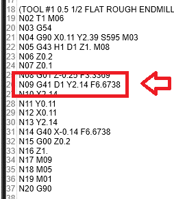
Once the feature is created, be sure to post out the program and check the g-code to ensure that the posted code does in fact post out the G41/G42.
If you need further assistance, please contact our support team at (727) 489 – 0003 or [email protected]