Knowledge Base Articles
- BobCAD-CAM V36
- Getting Setup
- Quick Tips & Tricks
- The BobCAD Basics
- Advanced Topics
- Computer Issues
- NC Editor
- Post Processor
- Our Forum
Setting Up The Machine Origin in BobCAM for SolidWorks
This document will help describe how to modify / create the machine origin for your Mill / Lathe / MillTurn / Wire EDM program (the machine zero).
These are a list of common issues that you may run into if this Machine Origin is not setup correctly
Common Issues:
- No Toolpath created (Z axis facing the wrong direction)
- Toolpath is referencing in the wrong center of rotation axis (4 Axis)
- Error in simulation (Collision between Tool and Table)
Machine Origin:
The machine origin is very important to understand because this is the origin that your g-code will reference and will be sent to your machine. You want to set up the machine origin in the same location that you have the origin (or machine zero) set on your machine.
Step-by-Step
For Mill / Mill Turn / Wire EDM:
1. Create a new job. Go to the CAM tab, right click on “CAM Defaults” and select “New Job”
2. Go through the job set up until you reach the “Machine Setup” page. (Alternatively, you can get back to this page if the job is already setup by right clicking on “Machine Setup” in the CAM Tree and selecting “Edit”.
This “Machine Setup” page, is where you will define your machine origin.
3. Scroll down to the “Setup Orientation” section and select “Pick Origin” if not already selected. (The box will be a blue color when active.)
Alternatively, you can select “Enter Origin” and manually type in your values with respect to the CAD origin.
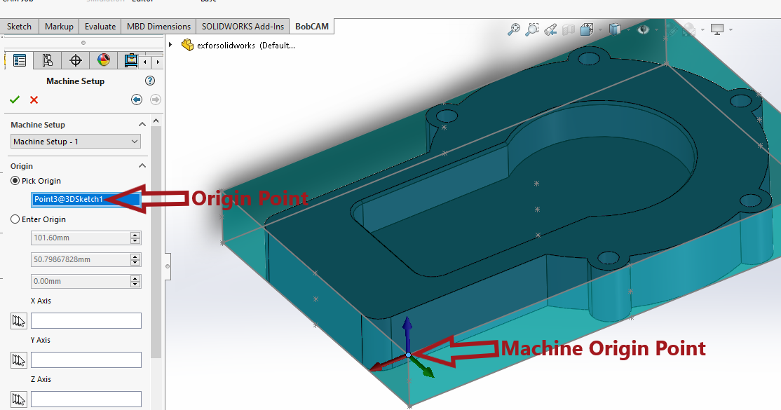
4. You can then select any point either on your model or from the bounding box that gets created on the edges of the stock.
Pic. 1 – Origin Point Selection

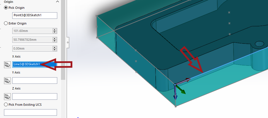
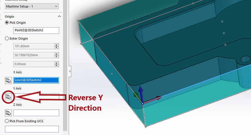
5. Once you get the machine origin point in the correct position, you can adjust the X,Y,Z axes with the X,Y,Z direction boxes. You can either simply click the reverse button ![]() to the left of the direction boxes to reverse the direction of the axis you want AND/OR click inside one of the direction boxes to activate it so that you can adjust the direction.
to the left of the direction boxes to reverse the direction of the axis you want AND/OR click inside one of the direction boxes to activate it so that you can adjust the direction.
6. Once you activate the box, click on the line that you would like the axis to run along (or a line that is parallel to the axis you want it to run along). You can also select a point that you want it to point towards.
Pic. 2 – Set X,Y,Z Direction

Pic. 3 – Reverse Axes

For Lathe:
1. Create a Coordinate System by going to Insert --> Reference Geometry --> Coordinate System. Set up the coordinate system where you are going to reference the machine origin.
2. Create a new job. Go to the CAM tab, right click on “CAM Defaults” and select “New Job”
3. Go through the job set up until you reach the “Machine Setup” page. (Alternatively, you can get back to this page if the job is already setup by right clicking on “Machine Setup” in the CAM Tree and selecting “Edit”.
This “Machine Setup” page, is where you will define your machine origin.
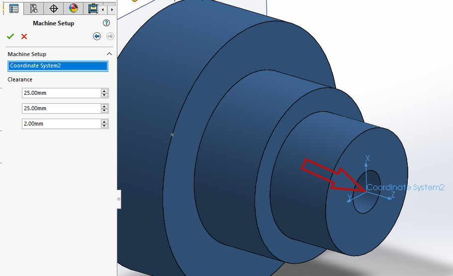
4. Click the “Machine Setup” box if it is not already highlighted and simply select your coordinate system that you created.
Pic. 4 – Coordinate System Selection

If you need further assistance, please contact our support team at (727) 489 – 0003 or [email protected]