Knowledge Base Articles
- BobCAD-CAM V36
- Getting Setup
- Quick Tips & Tricks
- The BobCAD Basics
- Advanced Topics
- Computer Issues
- NC Editor
- Post Processor
- Our Forum
Orienting a Lathe Part For a Job
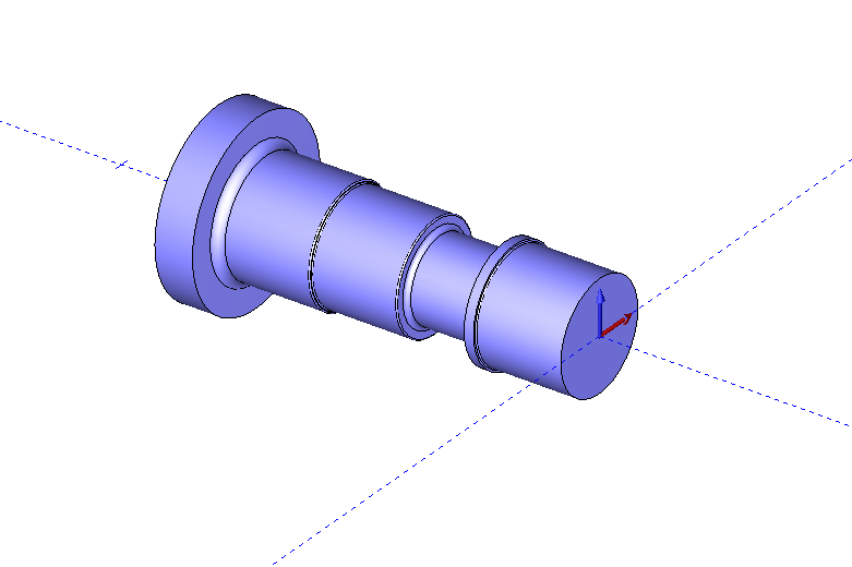
The lathe side of the software currently does not have the ability to move the machine setup to a specific location and so the user is required to orient all lathe parts to a specific location. The directions below will teach the user how to correctly orient their lathe parts, so that they can get good G-code when programming their part.
Pic. 1 - Example Lathe Part in Isometric View
All lathe part files should be placed in the second and third quadrant of the top view. To look at the part in the top view, click on the button that is circled in the picture below (Located at the top of the CAD Space) or press the Control + 1 keys at the same time.
Pic. 2 - Activating the Top View in the CAD Space
![]()
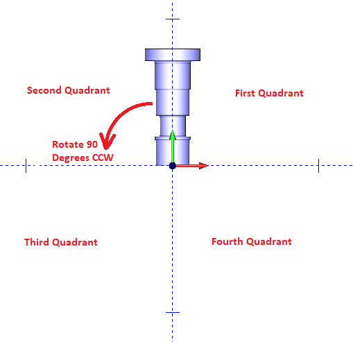
Picture number 3 shows the lathe part in the top view and because the part is in the first and second quadrant it will need to be rotated counter clockwise 90 degrees for the part to be moved to the correct second and third quadrant.
Pic. 3 - Lathe Part in the Top View
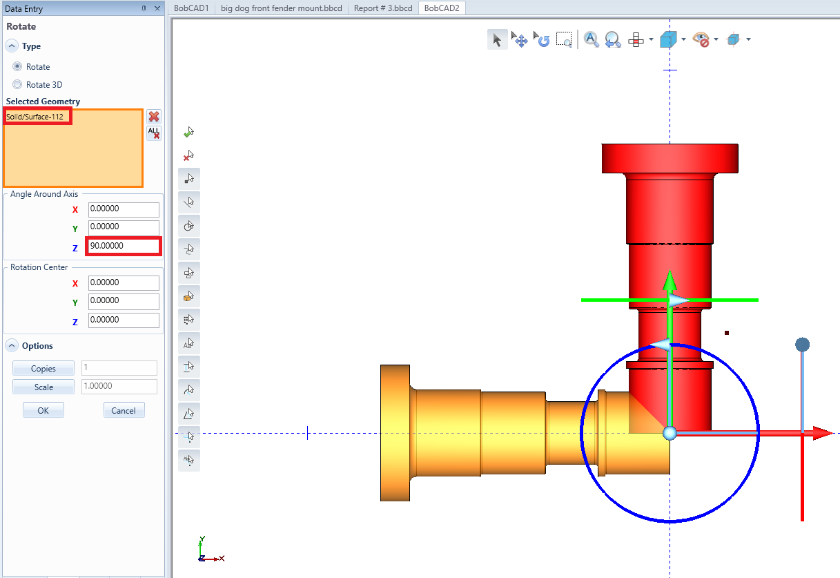
To rotate the part to the correct orientation, start up the rotation function by going to Utilities and clicking on Rotate. The first step when in the rotate function pops up is to select the geometry that is desire to be rotated. After selecting the geometry there will be red, green, and blue circles that will appear at the BobCAD origin. These circles show how the part rotates about the X-Axis (Red Circle), Y-Axis (Green Circle), and Z-Axis (Blue Circle). There are also arrows on each circle which will show the positive angle of rotation for each axis, once the correct value is known place the value in the “Angle Around Axis” of rotate function. In the example below, the part shown in red needs to be rotated in the +Z direction (Blue circle) by 90 degrees, after placing the correct value in the angle around axis a preview of the part will show up in orange to make sure that the rotate will be correct.
Pic. 4 - Rotating the Lathe Part to the Correct Orientation
Get a Outer 2D Profile of the 3D Model
For Lathe jobs, we use the 2D Profile of the Lathe part. There are a couple different ways you can grab geometry if you have a 3D model of your part.
Option #1
Converting the Solid using Section View
Option #2
Converting the Solid into a Spun Profile
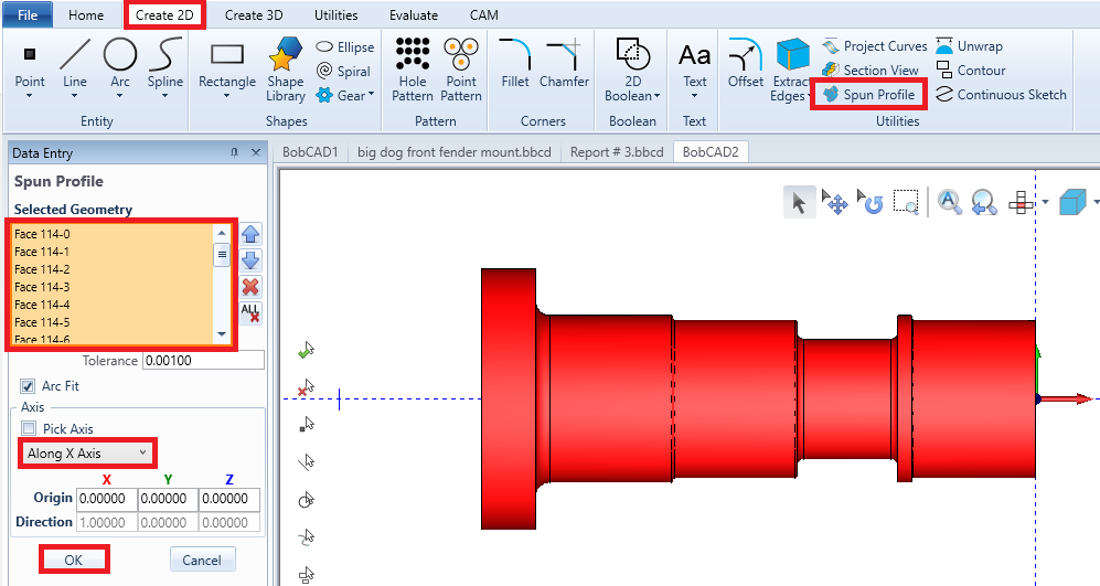
Alternatively, After rotating the solid to the correct orientation, the lathe side of the software requires the use of wireframe instead of a solid. To convert a lathe solid model into wire frame, the spun profile will need to be used which will basically un-revolve the solid into wireframe. To use the spun profile go to the Layers Manager and Right Click in the middle of the manager and hit “Add New Layer” (this will help to differentiate between the solid and wireframe later on). Now go to the Create 2D tab, select Spun Profile, select the lathe solid, and lastly before hitting the OK button make sure that the axis that the spun profile is un-revolving about, is the X-Axis as shown in the picture below. After all of this make sure to right click on every layer except for the one that was just made and hit the blank button so that BobCAD will just leave just the spun profile in the CAD Space.
Pic. 5 - Performing a Spun Profile
If you need further assistance, please contact our support team at (727) 489 – 0003 or [email protected]